Hi everyone!
i know it has been talked a lot but due to my poor knowledge of both english and electronics i have MANY questions! hope someone could help...
Let's start with this:
I would like to have (for example) ducktales 2 for the nes.
I looked at
http://bootgod.dyndns.org:7777/profile.php?id=1115
where it says:
LH231GHA Mask ROM 128 KB
CXK5864BPX-12LL SRAM 8 KB (120 ns
if i'm right the second is a RAM (not rom) so i don't have to put 2 eproms, just one, the MASK ROM.
Correct? Which game should i use as donor cart?
I was thinking about Silent Service which is a NES-UNROM too, but the sram chip is different... i mean, the size is the same, the company that made it not.
Is it ok?:/
Thank you in advance

Hi!
Silent Service (
http://bootgod.dyndns.org:7777/profile.php?id=438) will be ok for you to use, it has the same mapper, even the same 128KB ROM so it makes it perfect donor cart for Duck Tales 2. You don't have to worry about different writings on the chips, what's important are the parameters.
Burn the eprom with ducktales2 rom and replace the original rom in Silent Service and don't forget to do the necessary changes
http://nesdev.com/NES%20EPROM%20Conversions.txt
EDIT: you can click on the PCB class name in the bootgods database to see what other games use the same board layout/type/mapper -
NES-UNROM
Thank you:)
UNROM (mapper 2):
Bend up pins 1, 2, 24 and 31
Solder pin 2 to hole 22 (A16)
Solder pin 24 to GND (OE)
are these the only things i have to do or there is some implicit rule which i don't know?
Looking at the page you gave me i saw this:
CNROM (mapper 3):
No modifications nessesary
does this means i just have to put the eprom without pin bending and soldering wires? :O
I've never done UNROM, CNROM or NROM cartridges, but as far as I know, Yes, no modification is necessary. I've done SLROM and TKROM according to that instructions, and everything went well
EDIT: but I hope you know about prepairing the rom for burning (cutting the header) and using exact type of Eprom. In this case you need 128KB EPROM (27C010), or the instruction would have to be modified.
i think that editing the eprom will be not a problem (at least is hope so). Anyway i'm not at that point, i'm still in the "gaghering info" part
I was thinking that, since i am a beginner, i should start with REPROPAKs... I mean, before tearing apart some good games
but hey, i have questions even here

there are two models: repropak and repropak mmc1.
I'm pretty sure that with the second i can run mmc1 games... but what about the other? there is a table on the site (
http://www.retrousb.com/product_info.ph ... 1cec20bc68) that talks about 74HC32 and 74HC161. What are these? How to use them?
I have to say: this topic is really OBSCURE for me... if one good soul will explain really good how repropak works it will be really appreciated!
EDIT: I mean what do i have to do if i want to put ducktales 2 on a repropak? :S

Argh read the
MANUAL!
You can buy the 74*** IC's just anywhere. They represent the mapper.
yeah i know...but how to use them?i mean, i really can't understand how they work... are they filled with something? or they are just blank chips?
The 7400-series chips implement simple primitives in binary logic: AND gates, OR gates, latches, etc. You don't program them; they're like mask ROM in this respect. In this case, a 74161 is a set of four latches with a binary counter function, and the 74HC161 is the "high-speed CMOS" version of this. The AOROM, BNROM, CNROM, GNROM, and UNROM boards use the latches to store the current bank number and don't use the binary counter. The other chip is an OR gate, allowing part of the ROM to remain visible to the CPU at all times.
You'd buy a 74HC161, 74HC32, 6264 or 62256 SRAM, and a few 0.1 µF capacitors, and solder them to the appropriate spots on the board. Then you'd buy an appropriately sized 29F series flash chip, program it, and solder it on.
first of all thanks, second: i know i'm boring please be patient :/
Ok now i understand about mappers
the capacitor you are talking about must be put on the board or is optional? not a big deal, just to understand... I mean, it is expected to be there? or it is 'better' if i put it there?
Do you suggest to use flash instead of eprom? if so may i ask why?
i answer myself (i'm really sorry for the question now): the capacitors are needed, depends on which kind of cart/mapper you'll use.
Here i am again (don't hate me).
Will this be ok to buy? any advice will be appreciated:)
Dual Powered Willem PCB3.5 Programmer
http://cgi.ebay.it/ws/eBayISAPI.dll?Vie ... 244wt_1141
On NA, I've heard lots of badddddd stuff about willem or whatever. We have a programmer called the Pocket Programmer....it works well. It does upto 3pin chips, and I'm pretty sure can program over 27C040's....Never errors, okay software. Only bad thing is it's parallel port. They have a PPII and a PPIII I think, might want to look into those as they might have USB support if you need it.
In short: I recommend the Pocket Programmer.
it's just that where i live there is no real choice... i found that for a low price (including shipping). Looking outside europe is out of question, because of shipping and customs. Anyway i still look around for this pocket programmer.
If i can't find one i'll go with that willem, since it can write flash 29F010/20 too, and i think these are better than 27C010/20 because if i'm not mistaken i don't need an uv eraser...am i right?:)
Ahhh your going to flash? Thats fine. I'll let you know if the PP does that option. And I think I may be mistaken, I think we have a pocket programmer 2. I'll check that later and edit this.
And who knows, maybe you'll get lucky or someone released software for it that actually works good? ^_^
Ahh yes I know that flash doesn't need to be erased from light.
A In-Cart ROM programmer type thing? Thats a good idea.
Again, two questions!
1)i'm not used to capacitors. The manual states 0.1uF are needed. I looked on ebay and there are some diffrent kind... which should i use? are there some optimal parameters?
2)Same thing for resistors... There are many kind

Just as an example would these do the work:
capacitors:
http://cgi.ebay.it/100-x-100nf-Ceramic- ... 2286wt_907
resistors:
http://cgi.ebay.it/100-x-1k-Ohm-0-25w-C ... 028wt_1141
thank you all, again!
check the SI table for the prefixes:
http://en.wikipedia.org/wiki/SI_prefix#List_of_SI_prefixes
The 0,1 uF means 0,1 micro Fahhrad (and should be written μF = greek alphabet). 0,1uF = 100nF (nano Fahrad).
At resistors is the same, but could be sometimes a little confusing:
1R = 1 Ω (ohm in greek alphabet)
1k = 1 000 Ω
1M = 1 000 000 Ω
but:
R5 = 0,5 Ω
1k1 = 1 100 Ω
1M5 = 1 500 000 Ω
and so on... (check
http://en.wikipedia.org/wiki/Resistor for more info)
in your ebay link are 100 pieces 1000 Ω resistors, the 0,25W (watt) is "power", and you shouldn't be bothered by this number, 0,25 W is more than enough for such small voltage as is in your NES/FC.
Ok i got it, i think i understand... but someone told me i need capacitors that states "104". I don't know what this means :/
ANY capacitors which is 0.1 uF will be good? i don't have to care about V or W?
104 is similar to
E notation, in this case 10e4 pF. This is the same as 10*10^4 pF = 10*10000 pF = 100000 pF = 100 nF = 0.1 uF.
Page of examples.
Capacitors have a voltage rating; this must not be exceeded. In general, as long as its rating is greater than equal to the maximum voltage in the circuit, with a margin (say 20%), it's fine.
Your help is really appreciated! thanks everyone!
(i bought these
http://cgi.ebay.it/ws/eBayISAPI.dll?Vie ... 500wt_1156 )
For resistors, usually carbon composition, 1/4 watt are used. You can use 1/8 watt in many cases (they're smaller). Usually tolerance doesn't matter, so 20% is fine. The ones you linked are metal film, which have less variation in the actual resistance versus labeled resistance. These will work fine, though they might cost more than carbon composition. I'll leave it to you to determine whether the cost difference matters; I haven't bought them in years so I don't know. BTW, metal film are usually blue with colored bands, rather than brown/tan as carbon composition ones are.
Oh... your post just confused me
The price is not SO important (well, i care about it but if it's so low i can get through it).
maybe it's because i don't speak very well this language but i'm not following you.
The only thing i know is i bought these resistors:
1k Ohm 0.25w Carbon Resistors.
..and these capacitors:
0.1uF 63V Radial Electrolytic Capacitors.
I would just someone to tell me "yes they are ok" or "no, you have to buy xyz". I know it sounds 'arrogant' but it's really not my intention.
a big kiss to the first that reply
...just a hug to the second!
I still have little idea what these are for. Give a concise summary of what you're doing and it'll be easier to offer help.
Since i'm going to use the REPROPAK (from retrousb.com) i was asking which resistors and capacitors are needed
this because the repropak manual says they are needed
On a side note, post here for info, as ReacketBoy doesn't have as many knowledgeable people.
XD ^_^
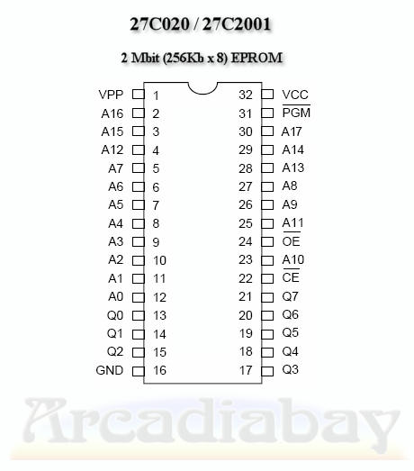
does anybody know the vpp voltage required to write 27c020 (and 27c010)?
playfortoday wrote:
does anybody know the vpp voltage required to write 27c020 (and 27c010)?

You builiding your own programmer? No need to WRITE to them, unless you are?
But anyway, just look up a pin diagram online....<includes links>
http://www.arcadiabay.de/images/elektro ... pinout.jpg
Look at the 256 PRG for the 256K NES mask rom pinout....
http://nesdev.com/NES%20ROM%20Pinouts.txt
I hope this helps.
No i'm not building it
i have a programmer with adjustable vpp...
I think it is set at 5V but i read somewhere that 27c020 needs 12.5V (or something else?). Is this true or 5V is ok when you write the eprom?
i can't find the command to dublicate the data.
i mean: if i have a 128K rom and a 256K eprom, how i dublicate the data to fill the whole eprom? is there a windows command?
thank you!! it seems to work!
i feel really stupid and i want to apologize again because i'm really boring and i make stupid questions.
But here is another one (hooray!).
How do i know if a hacked rom (for example FUNNY PRINCESS, hack of mario bros 1
http://www.thenesdump.com/screen%20shot ... incess.htm ) can work on a real cartridge? is there a way or i just have to test it?
If it runs in emulators, it probably work on a NES, unless it uses known emulator bugs.
The most concrete way to test it on a system is to just test it on a system.

Just testing it on a system fails to distinguish a faulty ROM from a botched repro unless you're using something like a PowerPak. I think playfortoday was trying to find a way to reliably distinguish the two without having to buy a PowerPak.
65024U wrote:
If it runs in emulators, it probably work on a NES
I wouldn't say that. It really depends on the emulator, but even the most accurate ones are likely to not behave exactly like the real console under extreme circumstances (like PPU operations at weird times during rendering). Some popular emulators (such as FCEU and its derivatives) don't even emulate the internal working of the PPU properly (things such as sprite evaluation and pattern fetches don't work like on hardware).
I think that the chances of breaking a ROM while hacking it are very high, because hackers never know if they are messing with sensitive code, since they weren't the ones that programmed the game.
I agree that the short answer is: You'll only know when you test on hardware. And even with the PowerPak you can't be 100% sure depending on the mapper, because not all PowerPak mappers behave exactly like the original ones.
YEAH! i made my first repro and it went all good! it was easy with the repropak:) it was a mapper 2 cart.
Now i'm having other problems because i would like to make some mapper 1 cart with battery support.
questions:
1)the manual says i need a diode. omg omg omg. what kind of diode should i buy?
2)This is where i have to put the battery (where the white circle is):

but how? :O
3)i have some battery holder that look like these:

Are they good?
Congrats in went fine, I can see a ReproMaker in the making!

But anyway, for the diode. I have no idea. The battery case should be the first one thin enough to fit. Unless by some miracle someone has a link to NEW ones with TABS. (I NEED some, if you do please post!)
Now just get into some assembly and your making new games.


I'm surprised the manual doesn't specify the part number for the diode. A standard small-signal silicon diode should do, like the 1N914 or 1N4148. I've used one of those in an MMC1 cart and they work fine. I've seen some suggestions to use a Schottky diode, as it has a lower voltage drop (0.3V versus 0.6V), but apparently also a higher leakage current. Avoid germanium diodes. I know you might not be familiar with all this, but I offer the information because you can't learn if you aren't exposed to things to learn.
Oh thank you!:)
i bought some 1N4148, hope they'll do the work:)
Now i have to understand where is the + pole and the negative one on the pcb... any suggestion with this?:)
that damned circle has 3 "solder spot"... umpf!
here's a better pic:

this is what the manual says:
Quote:
Solder battery holder to the backside
Solder a diode into the D1 space, with the cathode (end with line) towards the right
Solder a 1K resistor in the R1 space
Solder a diode into the D2 space, with the cathode (end with line) towards the left
Only install the battery when you are done soldering all chips
Keep the sticker in place, it makes sure the battery does not touch traces. It can be replaced with tape
Battery + side goes away from the board
It would make sense that they are on the top of the PCB, And in NES games, I think the battery plus side goes to the left on top so that would be on the right on the bottom, but it isn't a Nintendo NES board, is it?
Does it say where to get the socket from? And maybe be a little more clear with your question? And a full PCB shot might help, as maybe the right solder hole isn't there.
hope these can help:


I guess you need a surface-mount battery holder. Is there no parts list with the build instructions?
From those pics, it doesn't look like 2 of those big square pads are connected to anything, but I guess they must be connected to the copper filled area around it, which surely must be ground.
Yeah it's weird they didn't put it on top :/
I agree, surface mount battery holder, which I haven't ever seen ever, but they're probably out there. And according to
http://benheck.com/Downloads/NES_Famicom_Pinouts.pdf the leftmost pin from the top (36) is +5 and pin 1 is ground. While on the bottom, leftmost pin (37) is CLK (Not used on the NROM-256 board I am looking at) and the rightmost pin (71) is also ground. So somewhere on that board, one of those pins on the battery holder goes to the SRAM somehow. 0_o
It also looks that since there is no "Battery back SRAM" jumper that the battery is automatically hooked to the voltage pin of the SRAM somehow. Through the board trace?
65024U wrote:
It also looks that since there is no "Battery back SRAM" jumper that the battery is automatically hooked to the voltage pin of the SRAM somehow. Through the board trace?
Through a diode, wouldn't want 5V going to the battery when the NES is on.
Haha okay....that would be bad? -goes to read on how diodes work-
EDIT:
Okay from the picture, the diode connects to the battery to the left side, so would that mean the the left side of the under-side of the board is + for the battery? -is learning, too-
i have this battery holder:
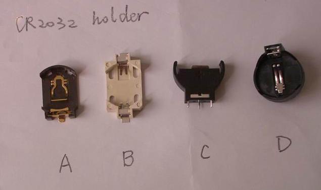
(note the photo is not mine, i have the model
D)
I'm sorry but in the manual is not said anything about this...
I just want to know where + and - are:)
I THINK (i really am not sure) that the first (on the left) square for the battery goes to a diode, then to a resistor and then to the first pin of the ram. is it possible?
Quote:
I THINK (i really am not sure) that the first (on the left) square for the battery goes to a diode, then to a resistor and then to the first pin of the ram. is it possible?
Yes, that's how it's connected on MMC1. For the picture of the solder side of the board, that would make the left square positive, and I'm guessing the right two negative (use a meter to be sure). Once you've got the holder soldered in, examine the battery and be sure the + really will go to the diode. You don't want a Li battery explosion.
+ is on the top and sides of the battery, - is on the bottom. So you can tell by seeing how the holder contacts the battery.
Quote:
For the picture of the solder side of the board, that would make the left square positive, and I'm guessing the right two negative (use a meter to be sure)
Ok so i connect the + on the left square but... how about the other two? Do i have to connect the battery to both? Just one? And which?:D omg:/
I have a digital meter but i'm not just new to reprocarts, i'm new to electronics
Blargg can you explain me what do i have to misure? I feel i really need a precise instruction...:/ Don't worry, take your time i'm not in a hurry
I think you have to get the battery holder on the cart, + on the left pin, and use the other 2 pads for the -, but I am going to take a guess that you can use either, but don't have to use both because they might be for just different holder types.
If thats the case, solder one in (Holder), add the parts the instructions say, add a RAM, put in the battery, play, test, then either be like "AWESOME! It works." or "It doesn't save!!! :/"
Use the meter's continuity mode. This tells when the probes are connected. This allows you to find out what's connected to what on the circuit. Visual inspection is not a reliable method, especially when checking that you've soldered something. The idea is to verify that the circuit is connected a certain way. It's the equivalent of testing a program after you've written it, to be sure it really does what you think it will do. Spend some time using the continuity mode to verify things on the circuit, so you get good at using it. Be sure not to fall for
confirmation bias, where you merely verify something you soldered is connected; also be sure it's
not also shorted to nearby traces.
i'm SO sad right now.
I made a cart with zelda outlands and it works but does not save
I tried to connect the battery in
every way using the 3 squares.
now the + is on the nearest to the diode, the - on the center.
I was doing misures: There's a little hole near the mapper (the chip pre-installed) which seems to receive power from the battery. if i touch it and i touch the first pin of the ram i can see 1.5V on the digital meter.
This is all i can tell because i really don't know what to do now.
plese, help :/
What makes you think that Zelda Outlands works on a NES? Try a game that's known to work, like The Legend of Zelda. I remember that Outlands ROM hack displaying garbage or something.
What voltage do you get between pins 14 and 28 of the WRAM chip? What voltage do you measure for the bare battery pulled out of the holder?
well.. i assume it works due the large amount of repros of that game...
anyway... battery 2,81V
from pin 14 to pin 28 1.38V
ps:there is not graphic garbage.. it even saves with reset only. it loose the saves with power off.
When you reset, there is still power to the CPU IIRC. So it's still keeping the RAM alive, just the CPU gets reset. Only power down can test it to make sure it works. And that voltage is supposed to be 3.0 volts, so I'd say get a new battery.
i tried with a bran new battery that was 3.34V...
You used a SRAM, right? If so maybe post pics, something might be in the wrong spot! If it's not much trouble. Not really needed but sometimes some stuff is easier to diagnose that way.
Yes i used the right chip. It was written on the repropak manual: i used a 6264. Can't take a picture right now...i will tomorrow if it usefull...
edit: the manual is this
http://www.retrousb.com/downloads/repro ... manual.pdf
Well....only thing that could be bad now is the chip its self if you did everything right. You have any more by chance?
What is the part number of the RAM? Often the part # has an L or LL at the end, which is the low-power version, for use with batteries.
playfortoday wrote:
anyway... battery 2,81V. from pin 14 to pin 28 1.38V
That doesn't look right. That's a 1.43V drop. I think maybe you put one of the diodes where a resistor should have gone, causing two diode drops from battery to memory.
The game saves fine on two emulators so i don't think that's the issue.
And i'm pretty sure i put the diode in the right direction. About the battery: i tried every combination possible (there are 3 solder pads on the back).
I put two pictures:


There are 2 wires floating (i tried to put a capacitor -the manual says it is not needed- but the removed it, i still have to desolder)
About D2 (2nd diode) the pcb was already like that when i bought (wired i mean). I tried put a diode there too but it was unaffective. Now the pcb is a mess because i tried so many thing i can't even remember.
and yeah i know i suck in soldering
On the directions from RetroUSB, it says you also need a Diode on D2. You just have a jumper. That might be a problem.
i don't want to be rude but
Quote:
About D2 (2nd diode) the pcb was already like that when i bought (wired i mean). I tried put a diode there too but it was unaffective
i just desoldered it after some try and put the wire back.
Do you think i can do this:

maybe i can try with the diode and the resistor too at first...
I mean, maybe with this method i can be sure if the saving works, right?
I don't think this will harm my cart... at least i hope so
Ahhhh, didn't see that sentence. Okay well I think you should leave the diode there there. And for the Mobile SRAM, I am not sure. It might be just a bad trace in the board seeing as the board looks like everything is right, but I have no idea. Maybe use the meter to test all the little pads the battery goes on to make sure that they are what you think and do goto the SRAM's pin 28.
Measure the voltage as it goes from the + terminal of the battery to RAM. You should see a ~0.7V drop after the diode, then no other significant drop to the RAM, unless your repro board for some reason puts two diodes in series. If you see a large voltage drop on the resistor, it means something is drawing excessive battery current.
The usual arrangement is for the battery to go through a diode (to prevent back current), and a resistor (to prevent excessive current draw), to the RAM power, and for +5V to go through its own diode (also to prevent back current when the cartridge is out of the NES). That jumper is likely where the 5V diode goes. You put a jumper there when you don't have battery RAM, and a diode there when you do have a battery, at least for MMC1 boards. It's unlikely this works any differently.
Also, don't just try random things. It leads to sloppyness and lack of careful observation, which are good ways to make no progress when debugging. The first thing I'd do is mark on the PCB the proper orientation of both diodes, so you won't ever put them in backwards. No sense in tempting problems; use whatever aids you can in reducing the chance for error.
Quote:
Measure the voltage as it goes from the + terminal of the battery to RAM. You should see a ~0.7V drop after the diode, then no other significant drop to the RAM, unless your repro board for some reason puts two diodes in series. If you see a large voltage drop on the resistor, it means something is drawing excessive battery current.
There are not 2 diodes... i'll try later to see how much it drops
Quote:
The first thing I'd do is mark on the PCB the proper orientation of both diodes, so you won't ever put them in backwards. No sense in tempting problems; use whatever aids you can in reducing the chance for error.
I'm sure i've oriented the diodes in the right way following the mmc1 manual.
The guy from retrousb just wrote me this:
Both diodes and the resistor are necessary. One diode protects the battery, the other prevents the battery from powering the rest of the chips. The resistor slows down the battery drain so it lasts longer.
Additionally depending on which SRAM chip you have you may need to rewire the chip enable pins. I think the board isn't wired correctly for an 8KB chip with two enables.
[/quote]
for the record: i tried that mobile sram method. It does not work: the game freeze.
Wow, extremely strange. It could be that the chip is dead. Thats the only thing I can think of. 0_o Wow.....weird.
Ok... i took a new mmc1 pcb. tried another game.
Just to test i made Faria.
IT WORKED. i REALLY don't know why THIS worked since i made the SAME things as the other board.
A dead chip? Bad rom? don't know. :/
ps:as always i thank you all.
Maybe the board was defective....? Wow, really strange. Glad you got it working though! How many more repros you plan on making now that you have it figured out?
If you only have one diode, then the battery is going to be powering everything when off, which would explain why the voltage at the SRAM dropped below 2V.
So you tried another PCB with a different game? How do you know that it wasn't the other game that was the cause? This is what I meant about sloppy testing. By varying the PCB and the game tried, you made it more difficult to determine the cause, so we're left guessing, is it the game, or is it the PCB, or soldering job? This is the kind of thing that makes me less-enthusiastic about offering help, BTW, seeing that it's just hacking around without a lot of careful attention.
Hey, wait a minute
I tried a different game, it's true. Because desoldering the other (zelda outlands) i accidentaly broke a pin on a chip.
I will try again to determinate if it was caused by the rom when i get another pcb availabe
I can't remeber if i did that but do you think that if i tried without a diode the battery could have damaged something? like, i don't know, the mmc1 chip? or the sram?
I have to say it was probably a bad soldering problem because with the multimeter i spotted some point that now (in the working one, faria) doesn't have any voltage passing through them; in the zelda one there was current passing there... I don't know if this is clear
Anyway now that i made a working one i know where to solder the battery!
If anybody need that:
Positive (+) goes, watching the rear of the pcb having the battery spot in the up/right corner, on the soldering square on the left. The negative (-) goes on the MIDDLE one.
Ahh, good info to have. And you might be able to solder the pin back on the chip, but it's probably only worth it if you NEED the chip and just can't get another. Lol.
So the one on the left was positive. Booyah.
I want one of these boards now. XD
sorry for the delay... i was really busy:) anyway the problem was not the rom. It was just the battery, since i din't know how to do it, i soldered it in the wrong way. Tested with the "battery knowledge thing" it all went good:) thanks to everyone:)
Awesome to hear you got it working.

