Seeing as the mighty Kevtris and bunnyboy have made amazing NES HDMI adapters (well, bunny's is a complete system), is there any hope for a SNES equivalent? There is even an
N64 adapter in the works.
Being that the SNES uses the APU, is that the main reason we haven't seen any work on an HDMI mod for SNES?
The SNES's video is generated in analog on-die, so unfortunately getting HDMI out requires ADCs or emulating parts of the PPU. Actually, hooking up the SNES's APU is the easiest part because it actually emits something that looks like I²S, the only problem is that it's at a nonstandard clock rate (≈32040 Hz).
The N64 natively emits 21-bit digital YCrCb, and the NES HDMI adapter takes advantage of that the the PPU can be tricked into emitting the 5-bit pre-CLUT color value.
lidnariq wrote:
The SNES's video is generated in analog on-die, so unfortunately getting HDMI out requires ADCs or emulating parts of the PPU. Actually, hooking up the SNES's APU is the easiest part because it actually emits something that looks like I²S, the only problem is that it's at a nonstandard clock rate (≈32040 Hz).
The N64 natively emits 21-bit digital YCrCb, and the NES HDMI adapter takes advantage of that the the PPU can be tricked into emitting the 5-bit pre-CLUT color value.
I believe that 32,000 Hz is a standard sample rate, wouldn't one solution be to slow down the clock rate slightly to a more compatible rate?
Also, how much lag would be introduced with a ADC designed for SNES analog on-die video? Is it possible to digitize the color and upscale the graphics to HDMI resolutions with only introducing Hi Def NES latency? Of course, things may be complicated because the SNES has six standard resolutions instead of one for the NES.
Yup. Replacing the 24.576MHz ceramic resonator used by the SNES's APU with the same frequency of crystal (plus ballast capacitors) is all that's necessary. (The ceramic resonators are both lower precision and, for some reason, tend to drift fast in the SNES).
And similarly, a VGA-input equipped LCD computer monitor already has a set of ADCs that are fast enough for this. (My monitor can even directly parse the SNES's output, if only the SNES didn't change the width of some scanlines.)
The only tricky thing would be dealing with the SNES's interlaced modes. I'd personally choose to ignore them; nocash says it's only five games that use it.
Are we sure that no signals going between PPU1 and PPU2 are suitable for snooping with the intent of capture? How about snooping VRAM reads as it pulls tile data for the next line?
Oh, sure, but that'd have more in common with snooping the NES's PPU's bus activity. It certainly gets us, I dunno, maybe 80% of the way there, but there's all the other bits in the way.
Great Hierophant wrote:
Also, how much lag would be introduced with a ADC designed for SNES analog on-die video? Is it possible to digitize the color and upscale the graphics to HDMI resolutions with only introducing Hi Def NES latency?
Oh, I failed to directly answer this. The amount of latency that would be involved here is trivial; typical high speed ADCs have 3 samples of latency, so the simplest naïve implementation could easily produce a letterboxed output with just 1-2 scanlines of latency on the emitter side.
Adding something like kevtris's HDNES circular buffer to scale it vertically to be full frame adds a little latency, but it's still less than 1 vsync's worth (16ms) .
lidnariq wrote:
Oh, sure, but that'd have more in common with snooping the NES's PPU's bus activity. It certainly gets us, I dunno, maybe 80% of the way there, but there's all the other bits in the way.
I was focusing more on the inter-PPU communication; a good chunk of them in the center have something to do with palette line selection (probing around shorting them out demonstrates this a little, for a lack of better tools).
Digitizing with an ADC can turn out very well IF the ADC is clocked to some multiple of the PPU's pixel clock. Once you have digital RGB from that process, line doubling is line doubling, so it can be done as laglessly as the NES HDMI project.
Would it be easier or harder if you were to use a 1-chip SNES?
lidnariq wrote:
The only tricky thing would be dealing with the SNES's interlaced modes. I'd personally choose to ignore them; nocash says it's only five games that use it.
I've vowed to use interlace if I ever make a mode 7 game because it's essentially free extra vertical sample resolution, plus it should in theory improve compatibility with newer TVs.
marvelus10 wrote:
Would it be easier or harder if you were to use a 1-chip SNES?
I've wondered that as well. If spying on the PPU is all that is needed, would it make it harder to do so in the 1Chip version? I kind of assume it wouldn't be easier.
tepples wrote:
lidnariq wrote:
The only tricky thing would be dealing with the SNES's interlaced modes. I'd personally choose to ignore them; nocash says it's only five games that use it.
I've vowed to use interlace if I ever make a mode 7 game because it's essentially free extra vertical sample resolution, plus it should in theory improve compatibility with newer TVs.
I had an HDTV that refused to show any color information over svideo from my snes. Yet the sdtv crt showed it fine (as well as the capture card). I also heard that the snes interlace mode isn't exactly to spec either.
lidnariq wrote:
...the only problem is that it's at a nonstandard clock rate (≈32040 Hz).
How are you coming to that conclusion? Because some random person(s) measured the clocks on their particular SNES and it wasn't exactly 32kHz? So what? I bet if I measured the output sample rate on my SNES it wouldn't be _precisely_ 32kHz either. One person's SNES APU output might be a little slower than 32kHz and another's might be a little faster. Again so what? None of that means it wasn't intended to be 32kHz by the original designers.
If I measure this 50Mhz oscillator I've got on my FPGA board here I can guarantee you it's not going to measure as exactly 50MHz on my scope. A huge number of factors come into play when measuring clock frequency:
Scope calibration
Scope probe impedance
Accuracy (ppm) of the oscillator
Quality of the oscillator
How many times is the input oscillator frequency being divided down before the point at which the measurement is taken?
How much is the input oscillator being divided down before the point at which the measurement is taken?
What method is being used to divide the input oscillator down before the point at which the measurement is taken?
blah blah blah
...the list goes on and on. In my 20+ years of computer engineering and fpga design I've never seen a single oscillator output a precisely perfect frequency. But no one cares. That's life.
And it would make sense for Nintendo to use cheaper oscillators since they were mass producing these consoles; even if they could save just a couple cents per oscillator at the sacrifice of a little accuracy you're talking close to a $1M in savings over the life of the console. I'm willing to bet the range of the 24.576MHz master input oscillator frequency is pretty large.
Update: Actually, in Anomie's apudsp.txt we have: "Note that this clock has been indirectly observed to vary, with rates of anywhere from 24592800 Hz to 24645600 Hz."
Whoa, hang on, looks like we've got an output sample rate of 32021.875Hz (24592800/768)! Sweet, now we know the _real_ frequency that Nintendo meant to use! Or wait...is it 32090.625Hz (24645600/768)? Or is it... Hey, what kind of super secret weird stuff is Nintendo up to now?!
These consoles don't need atomic clock levels of accuracy. Lol. No user is going to hear/see/feel the difference of a few Hz. The better question is: What was the most obvious _intended_ output sample frequency for the design? Does it make more sense that they intended some weird silly frequency of 32021.875Hz? Or does it make more sense that they intended it to be the standard 32kHz audio sample rate that the entire audio industry and the programmer's using it would be familiar with (within some reasonable tolerance to save money)? The answer is obvious.
jwdonal wrote:
These consoles don't need atomic clock levels of accuracy. Lol. No user is going to hear/see/feel the difference of a few Hz.
Unless you're trying to resample the audio to a rate that has a fixed ratio with the video rate in order to multiplex the S-DSP's I²S output with the video output. Then you'll end up having to generate the audio clock and the video clock from the same oscillator. Or will an HDMI sink correctly play audio at a varying rate of 32020-32090 or 48030-48135 Hz?
tepples wrote:
Or will an HDMI sink correctly play audio at a varying rate of 32020-32090 or 48030-48135 Hz?
I'm not sure specifically what you meant by that question but just to clarify for everyone, the variation in frequency would be from console to console (i.e. from oscillator to oscillator), not within a single console (i.e. single oscillator). It is highly unlikely that the frequency would modulate that much (i.e. 70Hz) within a single oscillator unless there was some power supply issue.
In any case, the best way to resample the S-DSP's serial audio output stream would be to have a source-synchronous design in which the HDMI SNES adapter board tapped into each console's own 24.576Mhz audio source oscillator and hooked it up to the adapter board's own FPGA. Then generate the div-by-24 (1.024MHz) clock off of that within the FPGA and resample the S-DSP's serial audio stream using that. In this way, you will resample the audio output samples at precisely the rate at which they were originally generated on every individual console regardless of its exact sample rate.
There is however one small caveat to the source synchronous approach for this particular application. You may likely run into the issue that the oscillator in the console cannot handle a multi-drop (i.e. multi-load) application. Most oscillators are meant to be connected to 1 and only 1 load unless they are specifically rated to support multi-drop. And note that multi-drop oscillators are more expensive than standard oscillators, so you're guaranteed that the oscillator in the SNES is not a multi-drop rated oscillator. Much more likely is the case that it was the absolute cheapest oscillator that Nintendo could buy in mass quantity - which is probably exactly why the oscillator frequency varies so much from console to console.
In cases where you want to use a single non-multi-drop rated oscillator in a multi-drop application you would want to connect the output of the source oscillator directly to the input of a multi-output clock buffer and then connect the outputs of that clock buffer to the loads (i.e. the S-DSP and the adapter board's FPGA). This is the only "safe" way to have multiple loads on a standard oscillator. Of course, you could always try it the cheap way and hook up the SNES' osc to both chips in parallel with no clock buffer and see if you get lucky too... Lol

With all that said I still don't think that's the best option for resampling the SNES' output because you're going to miss all of the audio mixed in from the cartridge (if any) and the audio mixed in from the expansion port (if any).
(Remember, there are 3 possible sources for the final mixed audio output from the SNES.) So you'd probably be better off re-sampling the final amplified analog output at 64kHz (i.e. the Nyquist) and call it good. You still have the option in this scenario of tapping into each console's audio source oscillator (keeping in mind the multi-drop caveat mentioned above) if you wanted to get a perfect re-sampling across all consoles. But worrying about losing a couple samples across the span of 32,000 samples is splitting hairs if you ask me. So what if you re-sample at 64kHz but the source content is 32020. Big deal. Of course, if the actual sample rate was 31980 then you'd be over-sampling for that console rather than under-sampling. (Note that the frequency can vary faster OR slower from osc to osc.) In either case, would anyone notice? Probably not. And note that if you're using your own oscillator input to the FPGA that your own oscillator is not going to be an exactly perfect frequency either. All of these reasons and more are why you almost never worry about this stuff in common practice unless you have some super-ultra-high-speed, super-precise application where you have to be spot-on. But in 99% of cases it's just not worth thinking about. Just re-sample the incoming data at twice the _expected_/_intended_ frequency (which in this case is 32kHz) and call it good. After all, what's a few Hz between friends?
SPDIF and HDMI audio sinks are known to reject (or at least seriously screw up) digital sources that aren't much closer than the 1permille error that the SNES APU's clock often has.
Injecting the correct 768×32000 Hz clock is the only correct answer.
Anyway, what peripherals actually use the SNES's expansion audio? The only one I already know of is the SGB (and its 3rd-party descendant that plays GBA games). You'd have to digitize the analog output there anyway, which largely defeats the purpose of keeping the APU's almost-I²S output all-digital until the final stage.
lidnariq wrote:
Injecting the correct 768×32000 Hz clock is the only correct answer.
It's not the only correct answer. There are multiple perfectly valid ways to accomplish this task as I mentioned above - just as there are in essentially every engineering task. Try telling a team of engineers in industry, "This is the one and only correct way to accomplish this task" and you'll get some good laughs.
But assuming by "injecting" you mean tapping into the console's 24.576MHz osc and hooking it up to the FPGA you can certainly do that like I said earlier (with caveats), but you probably don't want to drive the actual HDMI/SPDIF controller/output using that source clock. In fact, if you're using an external HDMI output controller chip you're guaranteed it's going to require some very specific clock input that is very likely not 24.576MHz. Lol. So no matter what you do you're going to have to cross clock domains at some point. Therefore, the best design practice would be to capture the samples into a bi-synchronous FIFO/RAM within the FPGA at the source sampling rate and then read those samples out of the FIFO using a completely separate clock generated internal to the FPGA using one of the FPGA's internal PLL cores so you can get a nice clean, accurate, and stable clock source to drive it out to its next destination.
Resampling is such a tremendously more expensive operation than just giving it the correct clock in the first place that I honestly can't fathom how you're seriously arguing this.
You'd need to reclock
everything in the SNES (much as Kevtris had to in the NES) to produce an HDMI-compliant signal. So you set the entire thing up to generate the data at the right rates in the first place. Otherwise you drop or interpolate samples or frames, and that's unambiguously suboptimal. Nevermind that downsampling can be a lossy operation, and at 32kHz we can hear the entire spectral content so losing anything would be unfortunate.
jwdonal wrote:
But assuming by "injecting" you mean tapping into the console's 24.576MHz osc and hooking it up to the FPGA you can certainly do that like I said earlier (with caveats), but you probably don't want to drive the actual HDMI/SPDIF controller/output using that source clock.
Why on earth would you assume that "inject" means "use"? Why would I talk about "injecting
exactly 32000 × 768 Hz" if I meant "use the output of the ceramic resonator"?
How would you handle Super Game Boy and MSU1?
lidnariq wrote:
Resampling is such a tremendously more expensive operation than just giving it the correct clock in the first place that I honestly can't fathom how you're seriously arguing this.
Um..say what? What tremendous amount of resources do you believe re-sampling requires? It's like 3 lines of verilog. Lol.
lidnariq wrote:
You'd need to reclock everything in the SNES (much as Kevtris had to in the NES) to produce an HDMI-compliant signal. So you set the entire thing up to generate the data at the right rates in the first place. Otherwise you drop or interpolate samples or frames, and that's unambiguously suboptimal. Nevermind that downsampling can be a lossy operation, and at 32kHz we can hear the entire spectral content so losing anything would be unfortunate.
Yeah...so none of that makes any sense. In any case, if you're using an HDMI controller like the AD9889B for example, you will have to resynchronize all of the data to a 165MHz clock. You don't just pick your own clock rates for Industry standard audio/video interface devices. :P
Really, it's just three lines of verilog for an arbitrary and dynamic sample rate converter that you can't know before you boot up? Because, you know, ceramic resonators and their sucking. You should expect drift as it gets warm, and you should significant age-based drift too. Just in case it's not obvious, I mean one that doesn't generate audible artifacts, none of this lousy "sample and hold interpolation" or "linear interpolation" BS.
Anyway, I still don't see why you're seriously arguing that resampling's a right way to do it. (Does it work? Of course it "works". So what? ZSNES "works" too.) Why on earth would you fail to put everything in the SNES on the same clock domain in the first place?
lidnariq wrote:
Really, it's just three lines of verilog for an arbitrary and dynamic sample rate converter that you can't know before you boot up?
Yes, that's exactly what I'm saying.
lidnariq wrote:
Because, you know, ceramic resonators and their sucking. You should expect drift as it gets warm, and you should significant age-based drift too. Just in case it's not obvious, I mean one that doesn't generate audible artifacts, none of this lousy "sample and hold interpolation" or "linear interpolation" BS.
You're making this incredibly more complex than it actually needs to be. What I was trying to explain before is that you wouldn't need to worry about any of that if you just tapped into the console's audio clock. Then you're re-sampler would always be using that console's exact source frequency. So it'll always be perfect. Or if you want to use your own clock you just need to make sure you re-sample at at least 64kHz (Nyquist) and you'd be fine - you could even go a tad faster if you're really
that worried about slightly faster oscillator frequencies from console to console. But personally I wouldn't even bother.
UPDATE: So just as a test I tied the analog audio out of my FPGA SPC player running on my DE2-115 and tied it into the analog audio input of my ML507, re-sampled the output with an internally generated 64kHz clock (and sorry, I lied, it was 4 lines of verilog, so sue me) and then drove those samples back out of the ML507's audio codec and hooked it up to some speakers. It sounded perfectly fine to me. Although I really didn't need to do any of that to know it would work - Nyquist/Shannon proved it would work back in the 1950s or something. Heh.

Hell, I probably could have done it in 0 lines of verilog if I just let the codec do all the work for me. Lolz. So I'm sorry, but for all your fancy technical jargon it's really just as simple as I said it was. I would also keep in mind that the original SNES audio source wasn't that high fidelity to begin with due to all of the compression/decompression/interpolation it had to go through before it even got to your ears. Bleh.
But if you really want to make this insane Rube Goldberg audio thinga-ma-jigger whatcha-ma-call-it then more power to ya!

You should be careful about "I can't hear anything wrong" tests with audio stuff.
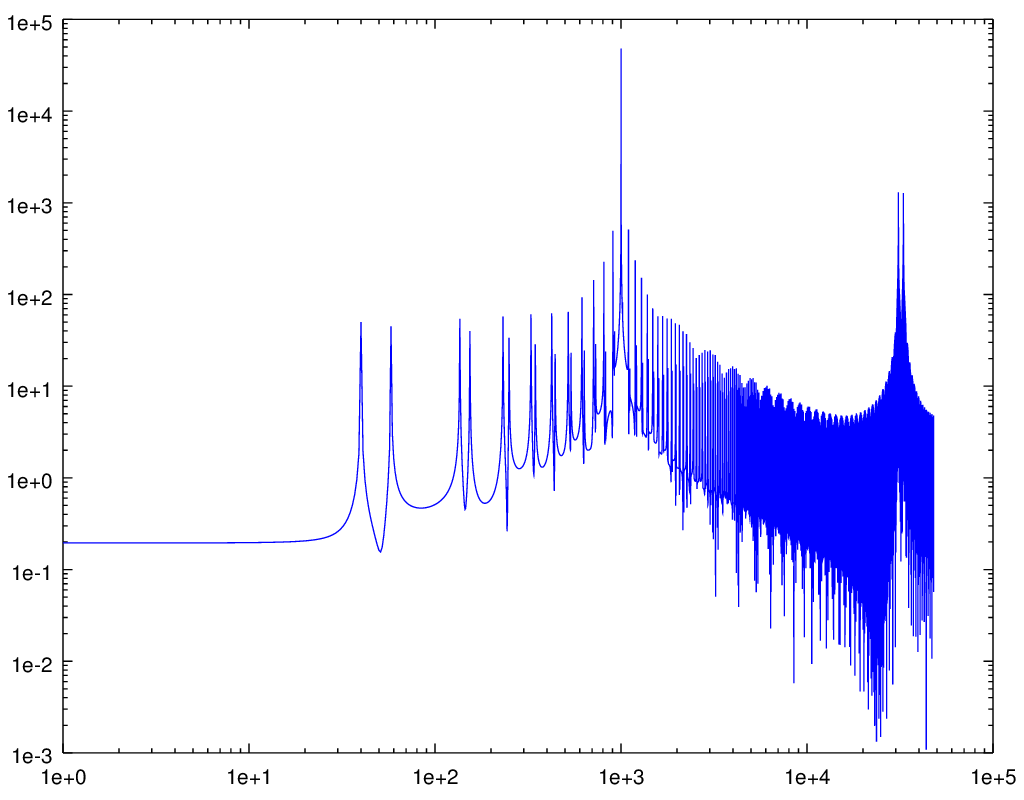
Since you say it's simple enough to be just four lines of verilog, it seems a safe bet that you're describing sample-and-hold interpolation. So here's what happens when you take a pure 1kHz sine at 32ksps; parse it as
32032sps 31968sps
(edit: braino), and upsample that to 96000sps using this sample-and-hold interpolation:
Attachment:
 sampleandhold.ogg [50.99 KiB]
Downloaded 128 times
sampleandhold.ogg [50.99 KiB]
Downloaded 128 times
The spectrogram (there's only about 40dB of rejection here, ignoring the ultrasonic portion):
Attachment:
 sampleandhold.png [ 14.8 KiB | Viewed 4314 times ]
The residual:
Attachment:
residual.ogg [57.16 KiB]
Downloaded 134 times
Just because you can't hear it doesn't mean the artifacts aren't there, and especially doesn't mean that someone else won't hear it. And
that's why I said that the
correct solution is using the correct clock in the first place, rather than something that produces resampling artifacts.
Here's the matlab/octave code I used to generate these:
Code:
inidex=[0:31999];
ssin=sin(inidex*pi/16);
outidex=[0:.333:31999];
ssout=interp1(inidex,ssin,outidex,"nearest");
loglog(abs(fft(ssout))(1:48000));
ssquant=round(32767*ssout);
save("sampleandhold.txt","ssquant");
ffout=fft(ssout);
ffout(1001) = ffout(95095) = 0;
iiout=ifft(ffout);
iiquant=round(real(32767*iiout));
save("residual.txt","iiquant");
Let's assume an adapter uses the Hi-Def NES approach, with the PPU feeding the upscaler through a circular buffer a couple dozen lines tall. Let's further assume that it doesn't provide for Super Game Boy audio. The adapter would feed a slightly slow master clock to the S-CPU and S-PPUs such that the frame rate slows from 60.10 to 60.0 or 59.94 Hz or whatever the TV expects. It'd also feed a precisely 24.576 MHz clock into the audio module so that the 32000 Hz output has a small integer ratio to what the TV expects. (A cubic spline interpolation circuit is probably easier to build with such a small integer ratio.)
At an average 1364*261+1362 = 357366 master clocks per frame, the S-CPU and S-PPUs would be fed a 21.44196 MHz clock to produce exactly 60.00 Hz, which is one part in 608 slow. If the APU is fed 24.576 MHz exactly, then from the game's perspective, the CPU:APU clock ratio would imply 32053 Hz, which is within observed limits.
Have there been experiments with under- or overclocking the audio module by replacing the 24.576 MHz oscillator with a variable frequency one to determine how games (mis)behave? Or perhaps putting the master clock through an 8/7 multiplier to produce 24.545 MHz?
Brainstorming a bit more about this mythical HDMA (high definition multimedia adapter):
The ADC to digitize Super Game Boy audio for mixing into the HDMI output wouldn't even need to be real expensive, as the Super Game Boy's output is about 6 bits per channel so you can get away without a lot of SNR. MSU1, on the other hand, might need something more expensive in order not to introduce noise.
tepples wrote:
Let's assume an adapter uses the Hi-Def NES approach, with the PPU feeding the upscaler through a circular buffer a couple dozen lines tall. Let's further assume that it doesn't provide for Super Game Boy audio. The adapter would feed a slightly slow master clock to the S-CPU and S-PPUs such that the frame rate slows from 60.10 to 60.0 or 59.94 Hz or whatever the TV expects. It'd also feed a precisely 24.576 MHz clock into the audio module so that the 32000 Hz output has a small integer ratio to what the TV expects. (A cubic spline interpolation circuit is probably easier to build with such a small integer ratio.)
Forgetting audio for a moment (since unlike NTSC video, analogue audio hasn't aged or become as difficult to utilize effectively) aren't we still stuck on getting digital pixel information from the PPU? That seems like the first hurdle that must be crossed.
So when I was hacking around with the expansion port (see snes-tap) I was able to passively snoop all reads and writes on route to the CPU/APU from my FPGA. With all this data snooped I had the FPGA forward it to my laptop through a FTDI USB 2.0 device. On my laptop I had a re-compiled version of Snes9x with the ability to grab the console data and emulate the video to show video representation of the console in emulator. I didn't spend too much time on it but the audio wouldn't be too much more work to get it going. In any case my point is one solution to the problem could be to take address bus B read/writes and use a 3rd party microcontoller (like a raspberry pi since it has HDMI) to perform snes audio/video emulation for the purpose of HDMI.
Given what you (mikejmoffitt) pointed out near the beginning of the thread, it seems likely that we could "just" monitor the inter-PPU bus ... but it seems likely that we'd still have to emulate PPU2.
Do we have an idea of what the division of labor is between PPU1 and PPU2 is?
defparam wrote:
So when I was hacking around with the expansion port (see snes-tap) I was able to passively snoop all reads and writes on route to the CPU/APU from my FPGA. With all this data snooped I had the FPGA forward it to my laptop through a FTDI USB 2.0 device. On my laptop I had a re-compiled version of Snes9x with the ability to grab the console data and emulate the video to show video representation of the console in emulator. I didn't spend too much time on it but the audio wouldn't be too much more work to get it going. In any case my point is one solution to the problem could be to take address bus B read/writes and use a 3rd party microcontoller (like a raspberry pi since it has HDMI) to perform snes audio/video emulation for the purpose of HDMI.
That's a possibility, but as that involves re-implementing the PPU and APU, it would be best to explore how much we can pull directly. There is also a discussion of latency that must be had with a higher level system like that.
The expansion port approach would require full PPU1+PPU2 emulation. But would be mod-free. It should produce a perfect image. The only issue would be added latency (it depends on how tightly you control the HDMI output. If you're using an RPi, it'd be as bad as a PC emulator's latency.)
If you were going to physically mod the consoles to remove chips, then I have no idea what you could do, but good luck. There's little documentation about all the exact interactions between the two PPUs, and later SNES revisions merge the PPUs into the same IC as the CPU.
Personally, my money's on an FPGA implementation of the PPUs through the expansion port, with a PC-emulator implementation as the proof-of-concept first. A mod-free adapter for HDMI video would sell like hotcakes. People are already doubling the price of SNES consoles with 1CHIPs for their ~10% better analog RGB quality. This adapter would obsolete nearly all of that market, and likely be even more valuable than the HDMI NES mods, but cost substantially less to produce.
The first person to market could probably easily pull in $200 a board, SNES console not included. The video quality would be vastly superior to even the XRGB, but you'd still have to charge less since it's an SNES-only solution. The NES HDMI mods have already shown that people don't care if the video processor alone is emulated, if it gets them crisp digital pixels.
Also, when it comes to audio ... the expansion port only carries analog mono. You would have to:
a) emulate the SMP+DSP as well to produce bit-perfect stereo audio (S/PDIF or the like)
b) grab the mono output only and output to both speakers
c) connect the expansion port board to the MultiAV to steal its audio signal
(c could also be a more stable source of Vblank timing than trying to snoop NMI through vector reads)
Once you're emulating the S-PPU1, S-PPU2, S-SMP, and S-DSP, you might as well emulate the CPU and DMA too and make a Super Famiclone.
tepples wrote:
Once you're emulating the S-PPU1, S-PPU2, S-SMP, and S-DSP, you might as well emulate the CPU and DMA too and make a Super Famiclone.
Like I said, people already emulate the NES PPU for the HDMI mods. Hasn't hurt sales any.
I'm probably the first proponent for just using a full emulator. That's what I've spent nearly a decade working on, after all.
But there's always a market for people who want to pay $300 for each loose game cartridge to run on their LCD TVs. And if you want to make some money, there's plenty of market demand here and absolutely no competition.
byuu wrote:
tepples wrote:
Once you're emulating the S-PPU1, S-PPU2, S-SMP, and S-DSP, you might as well emulate the CPU and DMA too and make a Super Famiclone.
Like I said, people already emulate the NES PPU for the HDMI mods. Hasn't hurt sales any.
The NESRGB and Hi-Def NES are functionally the same as ripping out a TurboGrafx-16's HuC6260 VCE (color encoder) while keeping the authentic HuC6270 VDC (which generates pixels as digital offsets into the palette). There's no analogous clean functional separation between S-PPU1 and S-PPU2 that I'm aware of. This means you'll have to emulate a
lot of the functionality of the S-PPUs, more than you would have had to with the NES PPU, and you might end up something that's at least as far away from the behavior of the normal 1/1/1 or 2/1/3 consoles as the 1CHIP is.
Is it really worth going through that effort rather than just sampling the analog RGB directly? The functionality is the same from the user's perspective (install mod in SNES, new HDMI port in the back), and there are some sampling/filtering tricks you can do to get damned close to what pure digital would look like (see HD Retrovision's proposed SHVC to 1CHIP processing for an example).
Obviously in the NES a pure digital approach made sense since there was no native RGB signal to start with, but in the SNES there is, and emulating most of the hardware inside the SNES just to get what could end up being an imperceptible improvement in quality doesn't make sense to me.
EDIT: It would also be a heck of a lot easier to install than an NESRGB or HiDef NES, seeing as how you wouldn't need to desolder anything, just solder R/G/B/S/L/R/VCC/GND wires.
We can already get a
component AV cable for the SNES, for an effectively no-mod situation.
Merely tapping RGBS/LR isn't going to provide meaningfully better video quality.
The real question for such a project is balancing whether the DRAM refresh noise in the video signal can be compensated for, or whether PPU2 is a reasonable thing to reimplement in an FPGA.
The HDR component cables, while a great option, have several issues:
- They're still passing 240p, and many displays don't handle 240p as well as they should. They typically try to deinterlace it poorly, thinking it's 480i.
- They're not digital, and that means many displays will add additional latency as they digitize and upscale (often using very blurry/distorting interpolation)
- They're not HDMI, and some televisions these days only have HDMI inputs
The cables are a great option to have: some televisions don't have any of the problems that I've mentioned above, and they're going to be way cheaper, and many more televisions have component input than the increasingly rare composite. But some people will just want the convenience of a standard HDMI plug that outputs a clean 1080p signal.
So, my argument is that what's being discussed (re-implementing most of the SNES on an FPGA) is not going to provide meaningfully better video quality either, not compared to a good RGBSLR to HDMI solution that is targeted specifically at the SNES and the quirks of each hardware revision. You can do a lot better than the framemeister in that regard. Compared to the analog solution, the digital approach is going to be an enormous amount more effort to design, and is going to cost a whole lot more to build. And if it doesn't go through the expansion port, it's going to be a whole lot harder to install, too.
EDIT: I mean to say that, you can take advantage of some known facts about the SNES, including the fact that each channel is intended to be only 5-bits, and being able to model exactly how much intensity bleeds into the next pixel on the same scanline. Conveniently, HD Retrovision has access to basically every revision of the SNES ever, and has already done something like this with a mind towards their HDMIzer project.
One of the big problems with the SNES and NES is that they generate NTSC-shaped video at 60.1Hz, and many HDMI sinks will reject (or cause visible tearing, or drop frames from) sources that aren't much more precisely 60.000Hz.
The best solution to prevent those problems is to slow down (i.e. replace) the NES/SNES's master clock, as tepples outlined above.
Is the clock source not provided by a crystal that can easily be replaced such that you end up at 60Hz? I'm not sure how that would be a roadblock, unless I'm misunderstanding the problem, or it's crazy hard to desolder them. I'm not sure why you'd need to re-implement all the hardware from scratch to change the master clock.
Alternatively, you could have your scanline buffer grow gradually over time and drop a frame whenever it fills up, which I think would be every 10 seconds. Less annoying than tearing.
One cannot easily get the requisite 21.44196 MHz crystal. You'll probably have to synthesize it with a PLL (in practice, the PLL in an FPGA).
But in any case, my real point is: You can get RGBSc/LR directly from the A/V port on the SNES. If your plan is "just ADC all that stuff", there's no need for a modification at all, just a special A/V cable.
BUT if you have a SNES that has a visible vertical bar due to the DRAM refresh, the magnitude of that noise is often more than 1LSB of PPU2's video DACs, and that's why it might be worth figuring out what exactly it is that PPU2 is doing and emulating that.
No, the plan is to not build a super famiclone inside a SNES shell
The idea is to avoid re-implementing key hardware if possible, and gain the quality improvements via targeted processing rather than a pure-digital path.
Guspaz wrote:
Is the clock source not provided by a crystal that can easily be replaced such that you end up at 60Hz?
You need to clock it slightly faster in games that use interlaced video, such as
RPM Racing. These are the frequencies that the FPGA would have to synthesize in order to generate video at precisely 60 Hz and audio at precisely 48 kHz (assuming 1.5x resampling):
Audio: 24576000 Hz
224/239 lines: (341*4*262-2)*60 = 21441960 Hz
448/478 lines: (341*4*525)*30 = 21483000 Hz
And possibly other frequencies during transitions among 224, 239, 448, and 478 line modes, as the PPU centers the 224-line mode by moving the vsync pulse up rather than by moving the picture relative to vsync
Quote:
Alternatively, you could have your scanline buffer grow gradually over time and drop a frame whenever it fills up, which I think would be every 10 seconds. Less annoying than tearing.
That's what my DVD recorder does, with its full frame buffer. It needs the frame buffer for MPEG-2 compression anyway, but it does add lag. And unless the upscaler runs 480i in an all-bob mode, it'll need a full frame buffer in order to weave 480i together.
Well, you need to look at how bad the problem actually is: as far as I know, only a small number of games use interlaced mode at all, and even then all but RPM Racing seem to use them just for menus, where frame drops aren't really an issue, and nobody would ever notice it. If you just adjust things to work for 224/239, then yeah, RPM Racing won't work, but we're talking about only one game out of 783 which would have sub-optimal performance.
As for transitions, if they're generally just happening going into menus, then dropping a frame isn't an issue, although if you explicitly don't support the interlaced timing, then there isn't any transition anyhow. And keep in mind that the framemeister just blacks out video for multiple seconds when the transition happens, so dropping a frame is a massive improvement.
The expansion port <> HDMI adapter would definitely eliminate the light vertical bar in the middle of the video output completely.
Still kind of surprising no one really knows for sure what causes it or how to fix it. Key bet is that it's related to DRAM refresh, but people have had varying degrees of success 'fixing it' by replacing the Vreg and/or caps on the board.
> And keep in mind that the framemeister just blacks out video for multiple seconds when the transition happens
Yeah, much as I love the space saving of an LCD ... I've gotta say I'm really not impressed with the XRGB-Mini compared to my PVM-2030. The latter gives a far better picture, with much richer contrast (obvious benefit of a CRT), has lower latency, hides the light vertical bar better, etc.
I also get this strange fade-in effect with the XRGB. When I go from a really dark screen to a bright screen, the bright screen is somewhat dim and fades in over 1-2 seconds. Definitely not there on the PVM.
If we were going all-out with an expansion port adapter, I'd want to tie it to something like adaptive sync so we could perfectly handle both video modes without ever dropping a frame.
...
Another thing I'm surprised no one's really worked on, would be a simple 15.5khz->31khz analog RGB adapter. The PVMs set you back $300 each plus another $200 for shipping from California. But there's millions of PC CRT monitors out there with VGA connections. I picked up a beautiful Viewsonic 23" for $20 from a local used computer store.
I know there's professional equipment that costs a fortune (and often can't make sense of 240p content), but this doesn't seem like it would be all that challenging to build inexpensively.
Isn't that exactly what Marq's scanline doubler does, although that's outputting 480p HDMI and not RGB? IIRC it has two scanlines of latency and handles both modes just fine. Costs far less than the framemeister too.
It's been almost a year, is there anyone still working on an HDMI solution for SNES and/or other systems from that era?
From what I've read, HDMI signals use a dot clock of 148.5Mhz, so maybe use a 148.5Mhz crystal and generate a 21441960 Hz clock with SNES master cycles being 6 to 7 HDMI pixels long.
148.5 MHz is presumably for 1920x1080 including blanking: 2200*1125*60. But you'll probably have to slightly slow down the Super NES clock as well, as the S-PPU normally outputs 60.1 Hz, not 60.0 Hz that the HDMI spec expects.
- Most games use double strike mode, which renders 262 lines of 1364 cycles, minus four master clocks every two frames, for an average of 357366 cycles per frame. To run it at exactly 60 Hz, you need to clock it at 21441960 Hz.
- RPM Racing and a couple others use interlace mode, which renders 262.5 lines of 1364 cycles, with no short lines, or 358050 cycles per field. To run it at 60 Hz, you need to clock it at 21483000 Hz.
- The PPU switches between 224-line and 239-line modes by moving the vsync pulse and holding start of picture constant, not by moving the start of picture and holding vsync constant. When a game switches between the two, you'll need to speed up or slow down the CPU and PPU until it's synced up again.
And you'll need to use a circular buffer to collect video lines. A single-line buffer (as would be used for a 240 to 480 line doubler) doesn't work for 720 or 1080, as 240 lines out of 262 is a smaller fraction than 1080 out of 1125.
So the basic architecture would look like this:
frequency synthesizer -> CPU and PPU -> ADC for RGB channels -> circular buffer -> upscaler -> HDMI muxer
analog audio from cartridge (such as Super Game Boy or MSU-1) -> ADC at 48 kHz
24 MHz frequency synthesizer -> APU -> upsample from 32 to 48 kHz -> add to cart audio -> HDMI muxer
tepples wrote:
148.5 MHz is presumably for 1920x1080 including blanking: 2200*1125*60. But you'll probably have to slightly slow down the Super NES clock as well, as the S-PPU normally outputs 60.1 Hz, not 60.0 Hz that the HDMI spec expects.
- Most games use double strike mode, which renders 262 lines of 1364 cycles, minus four master clocks every two frames, for an average of 357366 cycles per frame. To run it at exactly 60 Hz, you need to clock it at 21441960 Hz.
- RPM Racing and a couple others use interlace mode, which renders 262.5 lines of 1364 cycles, with no short lines, or 358050 cycles per field. To run it at 60 Hz, you need to clock it at 21483000 Hz.
- The PPU switches between 224-line and 239-line modes by moving the vsync pulse and holding start of picture constant, not by moving the start of picture and holding vsync constant. When a game switches between the two, you'll need to speed up or slow down the CPU and PPU until it's synced up again.
And you'll need to use a circular buffer to collect video lines. A single-line buffer (as would be used for a 240 to 480 line doubler) doesn't work for 720 or 1080, as 240 lines out of 262 is a smaller fraction than 1080 out of 1125.
So the basic architecture would look like this:
frequency synthesizer -> CPU and PPU -> ADC for RGB channels -> circular buffer -> upscaler -> HDMI muxer
analog audio from cartridge (such as Super Game Boy or MSU-1) -> ADC at 48 kHz
24 MHz frequency synthesizer -> APU -> upsample from 32 to 48 kHz -> add to cart audio -> HDMI muxer
Here's a thing I've been wondering. If the people working on FPGA's are working on PPU1 and PPU2 separately, and PPU2 is the only thing that is outputting the signal that goes to S-ENC, would it be possible to re-implement just PPU2 using known aspect ratio sizes?
eg 1-20x multipliers. 1080 is the only one that doesn't wouldn't work for pixel perfect, but presumably you'd want to either 4X it and live with the windowbox or 5X and crop it to 216 pixels (1080) or leave it at 1200 for WUXGA. 480 is 2x, 720 is 3x, 5X WUXGA, 9x UHD (4K), and 18X SUHD (8K)
Like, I don't think we are anywhere near that right now. A really blunt version of this would making PPU2's for 240,480,720,1080,2160,4320 if the logic in it is little more than "here's a map, copy the numbered tiles I already put in the VRAM treasure chest here" maybe it's only hardwired to do 240p and it's literately fitting it into other resolutions (what does it do on PAL?) One of those is the hires mode, yet 240 output. When I saw the field line in the pinout I was like "looks like maybe it supports telling the PPU2 to alternate between interlaced fields."
And as mentioned elsewhere, HDMI can be driven by a FPGA directly, which is essentially what they did for both FPGA NES systems from what I've seen and not a separate HDMI chip which IIRC requires an entire framebuffer and that's the reason for latency. A lot of other FPGA versions of 8 and 16-bit computers have run into a similar problem where they can't output a full color VGA signal over their FGPA board's VGA, but can't output >480p HDMI because they used low-cost FPGA's that don't have enough memory for the line buffer.
I might be wrong, but I would really like to see something, and up until late last month it seemed like nobody was working to save the SNES from going extinct. I keep looking at the price of the FPGA Dev boards and am I like "where am I going to hook up a real cart on this?" and "exactly how big of FPGA is needed?" I have to wonder where these clone systems get their cart and controller connectors from.