Background: The old board floating on nesdev was giving faulty results in the new Eagle, and did not conform with design specs for Laen's PCB ordering service. Of course this is odd since all I did was recreate the very same model, and it works fine.. although not as pretty.
I will be ordering pcb's in 3-4 days.. I estimate can sell some for $2-$5 each. Let me know if you are up
Nice!
I can't think of a use right now but I'll keep it in mind.
PCB Eagle Board :
http://www.mediafire.com/download.php?ampxqyj0ilrqm7tNOTE: the dip holes on this board are not big enough to fit my pin headers in. If you are downloading this board you want to fatten them.
Do you ship to Spain?
I would like around 36 units. How much will be?
jose found a site that will definitely save u $$$
http://www.buyicnow.com/fincat.php?cat=396
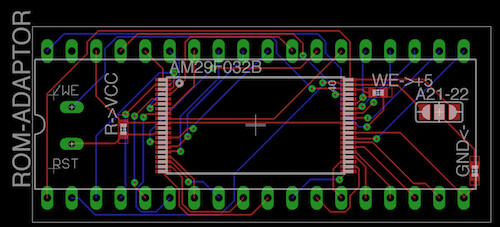
they have both the ROMLab pcb as well as the adapter on nesdev, which is truly the same thing as mine on this thread minus a pad for /We and /Reset that I added for personal shiz.
bazz wrote:
jose found a site that will definitely save u $$$
http://www.buyicnow.com/fincat.php?cat=396they have both the ROMLab pcb as well as the adapter on nesdev, which is truly the same thing as mine on this thread minus a pad for /We and /Reset that I added for personal shiz.
Those are not compatibile with snes carts, I have tried several of those.
really?? I looked at some pins and they seemed to match... do you know what is off?
Tormenter wrote:
Those are not compatibile with snes carts, I have tried several of those.
There's two different versions of the adapter in that link, which one are you saying is not compatible? Or are you saying both are incompatible?
I just ordered 16 of the type "II" adapters from them. I will compare them to the ones that I had Laen make a few weeks ago once I get them.
Guys I got the adapter in the mail today.. It looks great ..

BUT the drill size is a bit too small for the pin headers -.- Looks like I will be using wires again... lol ..wow fail
Might be a bit ghetto but what about sticking some piece of stripped uniwire cable in the hole and solder?
If I was making an SMT-DIP adapter, I'd do it like this:
http://www.seeedstudio.com/depot/serial-port-bluetooth-module-masterslave-p-572.html (with the DIP pads being on the edge of the board, solder it flat against the board). Having pins would be useful if you want to use a socket, though.
bazz wrote:
jose found a site that will definitely save u $$$
http://www.buyicnow.com/fincat.php?cat=396they have both the ROMLab pcb as well as the adapter on nesdev, which is truly the same thing as mine on this thread minus a pad for /We and /Reset that I added for personal shiz.
Anyone knows why A20 and A21 are inverted on the II adapter?
The I adaper is correct, at least according to my own understanding

bazz wrote:
Guys I got the adapter in the mail today.. It looks great ..
BUT the drill size is a bit too small for the pin headers -.- Looks like I will be using wires again... lol ..wow fail
I ordered a few and just received them and I must say that I had no trouble fitting pin header in mine. Not sure if you received a bad batch.
bazz wrote:
Guys I got the adapter in the mail today.. It looks great ..
BUT the drill size is a bit too small for the pin headers -.- Looks like I will be using wires again... lol ..wow fail
Are these the pre-made ones from china, or did you have some made by Laen? I noticed that the drill size on the ones I ordered from Laen were tight, but I was able to get a pin-header in there.
rkrenicki wrote:
bazz wrote:
Guys I got the adapter in the mail today.. It looks great ..
BUT the drill size is a bit too small for the pin headers -.- Looks like I will be using wires again... lol ..wow fail
Are these the pre-made ones from china, or did you have some made by Laen? I noticed that the drill size on the ones I ordered from Laen were tight, but I was able to get a pin-header in there.
ya from laen.. how the fuck did u get a pin header in there?
well, as I said, it was tight, but i did manage to get them in there. Then again, I did not use your eagle so I do not know what drillsize was defined.
I used some random brd file I found on the internets, and its drillsize was just about exactly the same as the pin headers that I have.
Guys, it's getting incredibly hard to resist making any "that's what she said" jokes on this thread xp
Lol.. so, bazz.. have you fired up one of these yet? I am running into an issue with my setup where all the M29F032Ds work fine, but the two AM29F032Bs do not.
I am wondering if you ran into any trouble with your AMD/Spansion parts.
so busy with school. but what kind of trouble are you running into -.- I hope i didn't blow my money on these chips....
Nope, I got one working last night. It looks like I have one defective chip from my lot of 12 that I bought on eBay. I also had one harvested from a piece of equipment that I may have damaged during that process.
A third chip that was never touched prior works perfectly fine. As of right now, I have 4 working M29F032D's and 1 working AM29F032B mounted on those Chinese carrier boards. I will be working on mounting more of the AMD/Spansion parts tonight.
Did you guy managed to have it working with the type 1 adapter from buyicnow? Because I have tried and even though I had no problem soldering the tsop, my homemade willem adapter can't ID the chip or program it. I'm getting frustrated and went over my adapter wiring dozen of time.
the adapter shouldnt matter, as long as the D0-D7 lines are correct and the supporting lines GND, Vcc, CE, WE are correct. All of the A lines can be in any A pin, as long as the final 36 pin output is the same as what the SNES expects.
If you are getting nothing but 00's off the chip, I would look at either a bad solder connection, or a bad chip. That is the problem I was running into with my refurbished AMD/Spansion parts.
I tried 2 different chip, same result. It look like it's erasing ok but then report device not empty when I do a blank test. The soldering job on the TSOP look perfect even with 30x magnifying glass. I wasted a day on that and still didn't managed to have the chip program or ID correctly. I'm using type 1 board and used peccost's willem adapter design (hand wired, not the actual pcb design). I also started trying with the type 2 board but wasn't sure what pad to short or if the resistor were mandatory. I shorted all the 3 pad but still same issue programming the chip.
on the type 2, you just need to jumper the three R locations, leave the three adjacent pads alone.
I know that I struggled with my first few adapters, but I managed to make 4 perfect ones in 2 hours the other night. Hang in there, you will get the swing of it.
I am most nervous about soldering the TSOP chip to the board.. I don't have great equipment. so for the first time I bought some solder paste and flux paste and plan on doing it over a skillet... but I realized i should have got flux LIQUID -.- . So I will just be using the solder paste.. I have never done this before I don't want to screw it up -.-
I found them very easy to solder using the pull technique and a small flat/angled tip. Use a lot of flux and it will prevent creating bridge. It's seriously fun to solder once you master the drag technique. Look on youtube as there's alot of video showing the drag technique for cleanly soldering TSOP IC. I'll have to recheck my adapter but im 99% sure my TSOP soldering job is perfect.
I have both paste and liquid flux. I personally prefer the paste as its easier to keep it where you want it. You can also use it to keep your part from moving around too much.
well I have a radioshack iron with a conical tip.. I've had it for like 7 years.. it just doesnt do the job.. and they dont sell other tips for this iron that I have :\
I have just checked and it doesn't seem that the /WE and OE/ line goes anywhere on the type 1 board (romlabs version). They are connected to the separate 7-pin row at the bottom of the pcb but they are not making any connection with the willem adapter which must have something to do with the chip not programming or being ID properly. Where should I connect those line on the willem adapter?
I made a homemade adapter with wire about 9 cm long running from the 36 pin socket (29f032) to the 32 pin header connecting in the willem following peccost's pcb design. Do you think the length could be causing the issue I am having? My willem is pcb v5.03. Sometime the chip appear to erase properly (giving me DQ7 success message) but then the blank test is unsuccessful following that erase session. The chip never send back a proper ID and display [----] and the manufacture code change from 0x00 to random one every once in a while.
I completely redid the adapter with connection shorter than 2 cm and even resoldered a new flash chip on a brand new pcb and made sure everything was perfect. Still nothing. I got one of my chip to id a few time yesterday but every time it would give back another id after and then no more correct id. Seem to erase but then fail blank check. Or it erase and give me success DQ7 within a few second which doesn't make sense. Then the willem software will suddenly give me an hardware error and ask to check power & connection and start working again a few second later or 5 min later unless I remove the adapter. I'm starting to believe there must be something wrong with the adapter as I saw people having exactly the same issue on a french forum (adapter were bought directly from the site). On the romlabs document for the willem adapter they list a 10nf cap and 2 2k2 resistor but it is nowhere on the Peccost design. I think that his adapter might work on some revision of the willem and not on other, that's the only logical thing I can think of. I'm started to think I wasted alot of money on flash chip for that project and I have wasted over 30 hour making different adapter and trying to find the issue so it is very frustrating. People interested in such a project should be warned.
I don't think the type 1 adapter is meant for programming the flash chip onto the snes board.
It works perfectly if you write the flash chip before and solder it afterwards!
Though writing shouldn't be a problem because all the unused pins of the flash chip like _W, _RP and _RB are on the left side, you just need to use them correctly.
I guess your adapter is broken or does not match, maybe you should read the datasheets.
Well, I have been trying with type II adapter too and still no result. I still don't understand how I managed to ID the chip properly a few time 2 days ago then nothing.
Do you have more than one adapter? you may want to try another board.
I bought 16 Type 2 boards, The first one I never got working. I soldered 10 more, 8 work perfectly, one works sometimes, and another just spits back 0's. All soldering is good, no shorts or breaks. I believe it may be a defective board, which for $0.65/ea is a distinct possibility.
I tried 3 type II board and 2 type 1. I made sure the soldering was perfect. I'm getting obsess over getting it to work and I'm thinking of buying a proper adapter for my willem as I'm starting to lose trust in that diy adapter. Why would it work with no component at all when the official adapter use some? Even the one from romslabs got sone resistor and a capacitor, I'm sure there is a reason for that...
neither my TSOP adapter, nor my TSOP carrier boards have any passives installed, just solder jumpers. Thusfar, I have had very few issues with them with the exception of some soldering issues and one that looks perfect but wont ID.
I doubt you got a damaged PCB, never happened for me.
Most common problem is a solder bridge, been there, done that

My soldering job on the tsop is close to perfect even under a jeweler 30x magnifying lens... I checked my adapter and everything match up with peccost's design and checked with continuity tester. Either my adapter is not working with my willem or i have 5 bad chip in a row. Isn't there some with an extra pcb for the maskrom to willem adapter? My sanity is at stake not to mention loss of sleep (keep trying to fix it until late at night on work day:) ) i don't have the supply to make my own PCB, Peccost say he doesn't sell them and they're out of everything at the french website that seem to deal a lot with repro and 29f032 adapter. People that do repro and sell them are usually shy of sharing anything that might give their "super power" to other

Picture:
http://www.skinnyv.com/images/tsop/
It look better in person though. The adapter look a bit ghetto but I tested all the contact with continuity tester. Also, I was thinking, isn't there a way to hack the willem software to add or modify a device's profile? It would be so easy to just change the 29f032 or add an extra device with the correct pin-out and address line for the maskrom adapter.
I had my Willem to TSOP adapter fabed with Laen's PCB service, so I have two spares. If you want, I can drop one in the mail, and you can try that adapter which I know works for me.
Man I would be so happy, I could remove my homemade adapter out of the equation and focus on what is really creating problem. Send me a money request to my paypal and I'll gladly pay you shipping for it and for the price of the item (if it's not too prohibitive)
Thanks a bunch for the offer, I'm getting crazy over this, not even because I have a super use for the flash chip but just because I'm get really annoyed and frustrated when something is not working like it should:) I redid one of the adapter again this time using my re flow gun (find it unpractical for that but worth a try), solder looked worse than my hand made job. I got full of hope when the chip id 2 or 3 time in a row, tried to erase the chip, it got done way too fast. Then it never gave correct ID since then.
Dont worry about the cost, I will mail it out probably tomorrow afternoon, since you are in Canada it may take about a week even though you only live about a 6 hour drive from me.
Very cool, thanks! I'm very grateful. I'll let you know once I get it, i'm sure it will be faster than that:)
That Japanese fellow in the other thread posted some pictures of his work, and it looks like they use Type-I adapters from buyicnow.
I notice that he has a jumper on the header on the end in all of his photos, for example:

Perhaps that is necessary to get them to kick over? Its worth a shot in your case.
Which thread? I can't see the picture. I'll go take a look at it.
Ediot: Ok I just found the picture and saw the bridge. I wonder why it's there but I wonder even more why he would need that huge thing with 6 27c801, 1 27c322 and 1 29f032 TSOP all on the same board on his SNES:lol:
Huh? What picture, what bridge? oO
the picture sometimes loads for me, sometimes not. It is on a Japan webhost, so perhaps that may have something to do with it.
You can right click on the picture, and either copy image or click "view image"
heh, it 403d for me the whole day, worked the first try with a japanese proxy
You need this bridge to connect W_ to VCC, otherwise the chip won't "boot". I would connect _RP too.
Oh right, didnt AMD/Spansion parts need that, but ST parts didnt? I seem to recall reading that somewhere.
I dont know, but it is always a good idea to disable W_ and RP_ for a game in a cartridge which is supposed to stay there

Hias wrote:
it is always a good idea to disable W_ and RP_ for a game in a cartridge which is supposed to stay there
Unless, for example, you're designing a homebrew game to use the last 0.5 MB of a 2 MB ROM chip for saved games.
How does this work? The 29F032 needs min. 12V to enable W_ access, where does that come from?
But great idea!
hello guys,that TSOP adapter1 bridge #reset to VCC.
I was trying few connection.
#WE is for use burning.

Hias wrote:
How does this work? The 29F032 needs min. 12V to enable W_ access, where does that come from?
In some flash IC families, it comes from a charge pump on the chip.
I'm really about to quit on these things. I soldered about 5 adapters, 2 of them Type 2. I can only get 1 chip on the Type 2 board to detect and ID properly. I seem to be able to read the chip, (at least part of it as I see copyright information from a company and data here and there) but impossible to erase. Re-soldered 2 other 29f0320 tsop to be certain the chip were not bad. Still no go. I checked the tsop legs with a 30x jeweler magnifying glass and it's perfect. Tried with a brand new SNES maskrom to Willem adapter PCB generously offered by rkrenicki and still nothing. I even changed my power supply for a 12v - 2A adapter and still nothing. I'm being paranoid about my willem potentially being the problem. If it's not the willem, I really don't know what it could be. I saw a lot of people posting about similar issue erasing around the net and one of the solution was to avoid an erase timeout by clicking in the device drop down box and leaving it open for a min or so because that apparently block the time out count while continuing to erase the chip but even that didn't work. How many people have had success with a regular willem, not the QG-4X or other True usb programmer. I'm talking about a plain willem 5.0. I'm going completely nuts over that thing and really starting regretting ever trying it out.
Just let your chip supplier program the TSOPs, every supplier should be able to do that for you.
I gothem on ebay and in any case, it would kinda defeat the whole purpose of using them as i want to be able to re-flash them by myself...
If I lived closer, I would offer to swing by to try my programmer, and/or my tested TSOPs.. But alas, a 6 hour drive in each direction is a little much for that..
Haha you were nice enough already to give me your adapter's pcb
I saw some people trying to program the same flash chip for a different purpose and he was saying he can program them if they are brand new but can't when he used second-hand flash chip that need to be erased so it might be a similar issue. I'm almost tempted to buy a new programmer but I can't really shell out 100$ for the USB programmer at this time of the year.
I just ordered another 24 chips and pcbs, I hope to have all of them assembled by the end of the week. I could test one and send it to you at my cost so you can rule out everything but your programmer?
That would definitly be very cool! But I would prefer you not have to pay anything this time so I could just send you a paypal payment and send you back the chip after. You are a really generous person and i wish I could pay you back at some point by helping you with something.
I received the chip today. Thanks a bunch! If you could just PM your paypal I'll be able to repay you for both time you shipped stuff to me.
I tested the chip right away, it get detected as M29F032 (my flash are AM29F032). So far so good! But the erase doesn't work. It start and get executed for what seem like 1 second then give me a ''Erase complete DQ7'' message but of course the chip doesn't past the blank test. So I really think I was right to suspect my programmer! I'll try to order a new one to test. I'll be shipping your chip back right after if you don't mind.
That chip was erased, blank checked, written, verified, erased again, and blank checked again just minutes before boxing it up. I can say that I am 100% sure that the chip is fully functioning. Again, that was with my GQ-3X
Don't worry about returning it, consider it a christmas gift, heh.
So, basically that one is doing the same thing that yours were doing? or is this kicking out a different error now?
As for the type of chip, I have about 40 of the AMD/Spansion parts, and 10 of the ST parts (well, now 9 since you have one) It should be IDing as 20AC.
Well, the problem I had the most often was the chip not being erased after ''erase by timeout'' message but I occasionally had the issue with the software giving me ''Erase Complete DQ7'' after just a second or so but the chip not being erased. I'm getting more and more suspicious of my willem being the problem and ordered a new one to be certain.
I'll keep you updated, and thanks a lot for all the help you are giving me. You are being very nice to a perfect stranger and I wish I had something I could get you to pay you back.
Hello I am new here, I want to follow the process to do the flash amd29XXX memory cart
I need someone to just confirm that I have understood right the tools I need and the process
Right cart donor
Eprom Programer
TSOP40 adapter
Pcb adapter
amd29XXX flash memory
Head pins
Process-
record ROM into flash memory
Solder Memory to PCB adapter
Solder pins to Right Cart donor
I quite not understood the bridge you have to do with the VCC and the W i think, can anybody explain that a little bit more.
To my understanding the pcb adapter is ready for straight forward soldering to the donor cart.
Also if you have more information on additional flash memories that are compatible with this process i will greatly appreciate it!
Thank you!
For 32mbit chips, without reinventing the wheel, only the AMD/Spansion AM29F032B and the ST M29F032D chips are compatible with the commonly available adapter.
I am sure you can design an adapter for just about any kind of parallel 32mbit flash chip, but those are the most common, and therefore least expensive versions.
For smaller games (up to 8mbit) the 27C801/27C080 are the most common.
It looks like there is a corrected Type II adapter, now called the Type III on BuyICNow.com.
From a quick glance, it looks like the A20 and A21 lines have been swapped back to be correct.
It work finally! It was the programmer I had, the 5.0e that was creating the issue, I bought a crappy looking old willem on ebay and it worked right away with the chip you gave me and my own. I have wasted so much time over this thing it's nice to finally know it was not me but the programmer. Thanks again for the help!
Awesome! I am glad that you finally got it working! do your own chips also work on the new programmer?
Yes they did on first try actually. That might be something to add to your website that some newer willem pcb version not from Sivana are having issue with the flash adapter. Now I only need to work a bit to have the romlabs pcb working, just need to verify again what pin to short on the extra connection to have them programmed. I only need to check the other thread as I remember the info was there.
I wonder if the issue was localized to your programmer, and not to the whole version. Perhaps a defective logic chip somewhere on there? Its been a while since I have seen an original willem adapter, but I seem to remember a number of 74 series chips, and perhaps a PAL or GAL or two?
Maybe but I programmed a few different kind of eprom and flash chip with it and never had an issue.
I got it today!
I cannot get and ID from the FLASH memory, I got it once and that's it!
When I click program the software shows the loading bar at 0% and never moves...
its says programming chip 49F00x but I have the settings for the AM29F032
jumpers are placed where the software tells me to...
I don't really know what to do :/
Help anyone?
I'm going to bump this thread with a question.
Was anyone able to get this pcb working from the files in the first few posts? I have some 29F032 chips flashed and I was looking for the right board to go directly onto the snes board.
Also, are the boards from china, the IC II and III adaptors, are those being used just to program the chips?
I have not carefully gone over the original designs, but they should be basically the same as the BuyICNow Type III adapter.
The Type III board is the correct one to take a pre-programmed 29F032 and mount it on an SNES board. You can also program it with that board using an adapter such as the one I posted for the willem.
So when I go to burn a file to the TSOP, from what i've read is that I leave the header. Do I also just change the file from .smc to .bin? Or is there anything special I need to do?
You leave the internal header (which is 32 KiB or 64 KiB into the ROM), but you have to take off the 512-byte copier header at the start.
Here's the end result of discussion threads like this:
People are selling fake Earthbound carts with boards like this now, claiming they are authentic.

Anyone here want to take credit for this one?
Not I, but that looks to be a slightly different layout for the TSOP board as the pads are much smaller than the ones I have seen. It would also appear to be a Laen board as it looks purple to me.
Couldn't you tell it was fake by the label?
That looks like it is an intel flash chip? Or perhaps its just a flux smudge that looks like a big "i".. If it is an intel chip, I guess that would explain the different carrier design. Perhaps a 28F320?
byuu wrote:
Here's the end result of discussion threads like this:
People are selling fake Earthbound carts with boards like this now, claiming they are authentic.
*image*
Anyone here want to take credit for this one?
This is very sad. But I think most of us knew this is what was going to happen.
lordloss, it is not that challenging to reproduce a cartridge label that is indistinguishable from the original. Plus if sold in an online auction, photos may not be detailed enough to notice this difference. Plus without the original side by side to compare it can be harder to tell.
It's really unfortunate that this sort of authenticity issue is now beyond the NeoGeo MVS world where it has been common for quite some time when selling a cartridge to want to see the actual PCBs to be able to verify that it is not a bootleg.
Ofcourse the high prices in the collectors market help create this problem too.
Where did this cart come from?
byuu wrote:
Here's the end result of discussion threads like this:
People are selling fake Earthbound carts with boards like this now, claiming they are authentic.
Anyone here want to take credit for this one?
I beg to differ...the end result of threads like this is that people are able to run whatever code they want on the SNES hardware.
If people take that liberty and abuse it by creating counterfeit merch, that isn't the fault of threads like these. That is the fault of the counterfeiter's lack of morals.
Do not blame the information.
dext3r wrote:
Do not blame the information.
Except since the mid to late 1990s, the trend in worldwide legislation has been to blame the information.
If nuclear or biological weapons became so easy to make that anyone in a high school chemistry class could do it, would you want that information to be public for all? There are some things that the public should not know, because there are too many psychopaths in this world.
In this specific case, I don't really care. At the rate Earthbound prices are going (and already at), even sticking a programmable flash cart inside another clamshell with a fake sticker would be massively profitable.
The only thing that is going to fix this issue is people coming to their senses. Earthbound is not a rare game at all. Fun 'n' Games is the rarest game sold at retail, and you can get that for $25, because it sucks.
If more people would just refuse to pay $300 for EB and instead go the flashcart route (you're not costing Nintendo any money since they aren't selling it, experience is 100% identical), the prices would drop.
To be fair, the people paying those outrageous prices are collectors. No normal player is going to pay that insane amount of money. These same people would probably buy a quality bootleg willingly. So I guess it doesn't matter too much, a collector would be pissed off if they bought what they thought was legit and found it was not, but I am not someone that would pay $300 for a game. Plus I think Earthbound isn't worth more than maybe $30. I don't see why people think it is so great.
byuu wrote:
If nuclear or biological weapons became so easy to make that anyone in a high school chemistry class could do it, would you want that information to be public for all? There are some things that the public should not know, because there are too many psychopaths in this world.
That is an extremely unfair comparison. Reproduction carts, even fraudulently sold ones, are in no way physically dangerous.
Should we also stifle talk about paints and brushes and artistic techniques in making pieces of art because someone could use that information to fraudulently make a reproduction of a famous painting and try to sell it as such?
MottZilla wrote:
To be fair, the people paying those outrageous prices are collectors. No normal player is going to pay that insane amount of money. These same people would probably buy a quality bootleg willingly. So I guess it doesn't matter too much, a collector would be pissed off if they bought what they thought was legit and found it was not, but I am not someone that would pay $300 for a game. Plus I think Earthbound isn't worth more than maybe $30. I don't see why people think it is so great.
I'm a collector and I know 2 people who are gamers and play these old games to play them and because they enjoy them. They both have an earthbound, from ebay, and I do not. EB is actually not that hard to find, just expensive because of the people wanting it, not the collectors.
But the problem is it is "perceived" as rare.
Not by the collectors though.
MottZilla wrote:
But the problem is it is "perceived" as rare.
With most commodities, this is fixable: another supplier introduces a close substitute to shake up the perception. It's happened with Scio Diamond (which bought Apollo Diamond in 2011) as an alternative to the De Beers cartel and its "blood diamonds". The difference here is that copies of works of authorship hold a special place in developed countries' law, making close substitutes impossible to provide lawfully in some cases, and the problem is that Nintendo appears to want to feed this perception of rarity. And I don't think there's enough free time for fans to develop a "spiritual successor".
So, is there a way to program the TSOP chips when they are already on the adapter?
I was looking at the pre-soldered AM29F032B on the DIP36 adapter, and if I can just plug that into my G540 and program it, that would save me a lot of time and effort in making a couple of dual-language carts out of some Japanese SNES games I have.
Sure there is a way, I have posted an adapter for the Willem based programmers, but I am sure it can be altered for other types of programmers as well.
I do all of my carts that way, mounting a tsop on a BuyICNow carrier, and then programming them.
I looked at your post history, and I'm confused.
Are you talking about the extended address header board, or the old TypeII TSOP adaptors that swapped A20/A21 on the TSOPs?
If it's just a matter of swapping pins, I can construct my own adaptor with a breadboard and an extra ZIF socket.
If it's the extended address header, the MCUMall website says the newer willem programmers don't need it.
I have a cheap G540, so I'd have to do some research to see if it could program a TSOP via the dip36 adapter.
For the extended address, the pin on the 40 pin zif socket of the GQ-4x are as follow (found by trial and error
)
A19 = PIN 4
A20 = PIN 37
A21 = PIN 38
It might be the same or similar for the G540 if you're lucky.
so if I were to make a converter, I'd just need to make sure the TSOP package's A19-21 are on the right pins for my programmer?
I assume every other pin is 1:1?
