So i of course broke the HSYNC signal for my Gameboy (hardware, not talking about emulator here).
Probably i might have touched other pins at the same time, or i grounded it wrong or something (noob at electricity).
What's weird is that everything else works, i can actually get an image if i grab the signals and decode them myself (by just ensuring it's 144x160).
And the audio is fine as well.
So it seems nothing is broken internally, but there's just no HSYNC signal at all from what i can see, and it makes no sense if it actually broke some chip as then i would assume some other stuff or the entire thing would break.
So i wonder if it might just be some component (capacitor or whatnot).
Hence asking here as ppl hare quite familiar with the hardware and might give tips on how i can troubleshoot:)
Anything is helpful, i don't have high expectations of it being fixable, but i also don't think it's completely broken either.
Thanks:)!
Two likely possibilities:
1- You broke some portion of the electrical connection from die - wirebond - leadframe - contact. Repairable, but depending on where could require some very specialized equipment.
2- You destroyed the pin driver. You *might* have destroyed only one of the pullup or pulldown; try adding a large resistor from the pin to +5V (or to gnd if the pin is instead always high)
I can't seem to detect anything that's broken visually at least (like burnt off), but then again it might be hard to detect.
Should i just connect the HSYNC to ground? wouldn't that just make nothing reach the LCD?
Not seeing anything broken more or less only eliminates "you didn't break the pin off outside the epoxy package".
What did I say that sounded like "just connect the HSYNC to ground" ?
lidnariq wrote:
Not seeing anything broken more or less only eliminates "you didn't break the pin off outside the epoxy package".
What did I say that sounded like "just connect the HSYNC to ground" ?
here:
or to gnd if the pin is instead always high)
EDIT:
okay assume it was about HSYNC pin, didn't think what you said when you said "pin driver".
Where is the pin driver, and just to make sure, it's simple where the signal is generated right? (wouldn't it be from the cpu?)
lidnariq wrote:
try adding a large resistor from the pin to +5V (or to gnd if the pin is instead always high)
Anyway.
Pin driver's on the DMG die. Consists of a big nMOSFET and a pMOSFET. Not directly repairable.
As I was saying, it's possible (given that the rest of the CPU is working correctly) that only one of these two MOSFETs is damaged. If so, adding a small current source (i.e. resistor) to replace the broken MOSFET would allow you to exchange a little more power consumption for a valid digital signal out.
A bit confused, where would i add this resistor if the Mosfet that's broken is on the die:s?
To me a resistor would prevent current, not act as a little booster. But then again i am very new to electronics.
Thanks;D
A MOSFET is a device that acts like a little switch.
Each of the outputs of the DMG are conceptually something something like this:

When the pMOSFET is on, the switch is to one side, and the pin is pulled high. When the nMOSFET is on, the switch is to the other side, and the pin is pulled low. The thing I'm suggesting is
perhaps, if you're lucky, only one side of the contacts are broken.
If so, a resistor would then make it act something like
a pull-up resistor (or its logical inverse, a pull-down resistor). The resistor is always "on", but only a little, and much more weakly than the MOSFETs themselves can pull the pin high or low. (Obviously, you need to choose the correct size of resistor for that to work)
So basically i want to make the mosfet have a voltage to it's gate very near the "open" voltage, so just a little boost from the device itself would turn it on?
hmm, or wait that doesn't feel right.
I know a bit about mosfets, but i mostly just understand them as P-Channel = give volt and it closes, N-Channel = give volt and it opens.
You don't have access to the MOSFET gates—that's further inside the die.
a pMOSFET-nMOSFET pull-pull pair ("totem pole") usually is connected something like:
Code:
positive supply
|
+-o|[--- positive supply
| |
input --+ +-- output
| |
+--|[--- negative supply
|
negative supply
You'll notice that this also looks like an inverter (it is).
IF one of the transistors is broken and permanently off, then you can get a valid logic level out of the pin by replacing the broken transistor with an external resistor. You just have to choose a value of resistance that is large enough to not overly tax the other MOSFET, but small enough that the output voltages still change fast enough.
Not familiar with inverters sadly, it kinda looks like transistor and opamp or something when i look at your code there O.o.
Hmm, but where do i connect the resistor in order to nodge that mosfet?
probably super obvious but kinda lost when i see the mosfet being on the die, the hsync pin being outside, and then there being a resistor that has to nudge the driver for the thing xd.
Is it supposed to be anywhere between the 5v and gnd?
that can't be right though, as that would mean running on batter could get it running when the volt decreases, or maybe not, embarrassing how crappy i am at this xd
Both kinds of MOSFETs are devices for causing current to flow:
Code:
nMOSFET
drain
|
gate--|[--- body
|
source
pMOSFET
source
|
gate--o|[--- body
|
drain
In both cases, current flows when the voltage from the gate to body is appropriate.
("appropriate" varies; for an enhancement nMOSFET it means "is sufficiently higher than the body voltage"; for a pMOSFET it means "is sufficiently lower &c"
In practice, these details don't matter: The pin
used to have a way to drive the voltage high or low, and now at least one is broken.
If you're lucky, and only one is broken -- and we still don't know that -- then you have a device that can pull the voltage only one direction. Adding a resistor in the opposite direction would at least let you see what the remaining MOSFET is doing.
I got a ton of different resistors ready, how would i measure to see what the Mosfet would be doing and where do i connect it?
(I got no oscilloscope, but got multimeter and analyzer).
Use the multimeter to measure the DC voltage on HSYNC while the gameboy is on.
If the voltage is 0V, then connect a ... let's say 100kΩ, because that's big enough to definitely not damage anything ... from +5V (NOT from the battery; from the flyback converter output or anywhere else downstream that you can get the regulated 5V)
If the voltage is 5V, then connect this same resistor instead to ground. (All the grounds inside the DMG are the same; just be careful to avoid the -19V from the flyback converter)
Once the resistor is installed, measure both the DC and AC voltages on the HSYNC pin. If the DC voltage is neither 0V nor 5V, and the AC voltage is not 0V, then great! One of the two output transistors still works.
If you are now getting a signal, the next thing is just adjusting the resistor so that you can get a useful digital signal for whatever's afterwards. An oscilloscope would make this part easier; then you could actually literally just watch the HSYNC pin and see if it got high/low enough fast enough. Otherwise, you kind of have to guess (e.g. does your voltmeter provide a "true" RMS voltage?)
Ah okay.
I have checked between the HSYNC and Ground, and there is 0 volt when the GB is on, so i will have to try connect a resistor to 5v regulated.
Where does that occur, is it the daughter board?
I usually power my GB via an USB 5v i soldered to the battery (if that has any impact).
My multi-meter sadly doesn't have any RMS mode:(
You can get the regulated +5V from the DMG CPU, or the RAMs, or the link port, or the link port protection diodes.
Probably other places too, but those are the first ones that stick out for me on Jeff Frohwein's schematic.
Hmm looking at the schematics, how would i know where it's actually on the board.
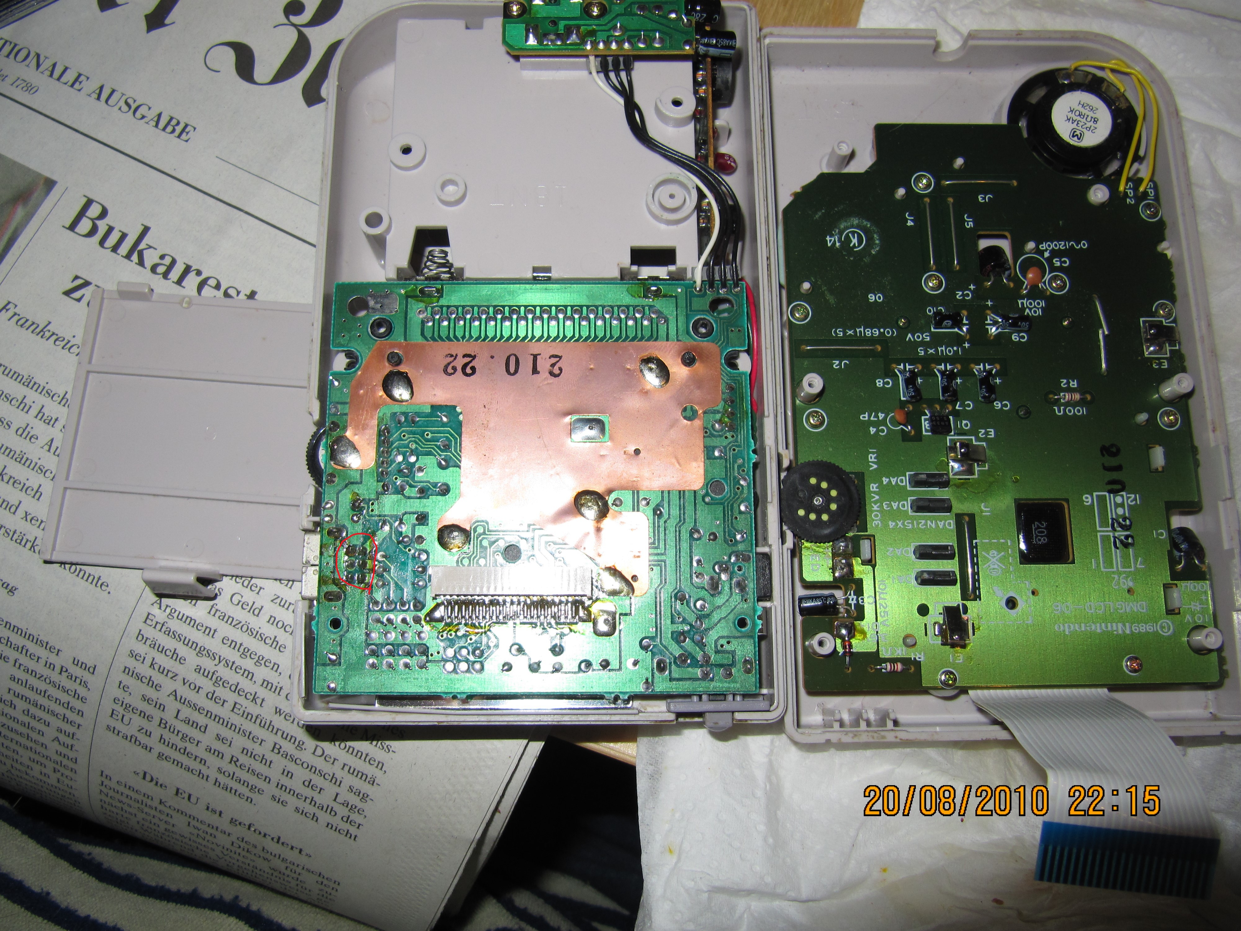
Are the Link port pins here:
https://abload.de/img/gameboy_innen_img_0179su73.jpg ?
Yes.
It's also on the LCD connector ("VCC")
Okay connected HSYNC to the VCC on the Link connector (Pin 1, opposite of Ground i hope).
Then i check with the multimeter on each side of the resistor, i get no DC voltage, and AC (set on 200) get about 09.1, i guess that's a good thing?
EDIT:
or wait, maybe i was supposed to check between HSYNC and Ground lol xd
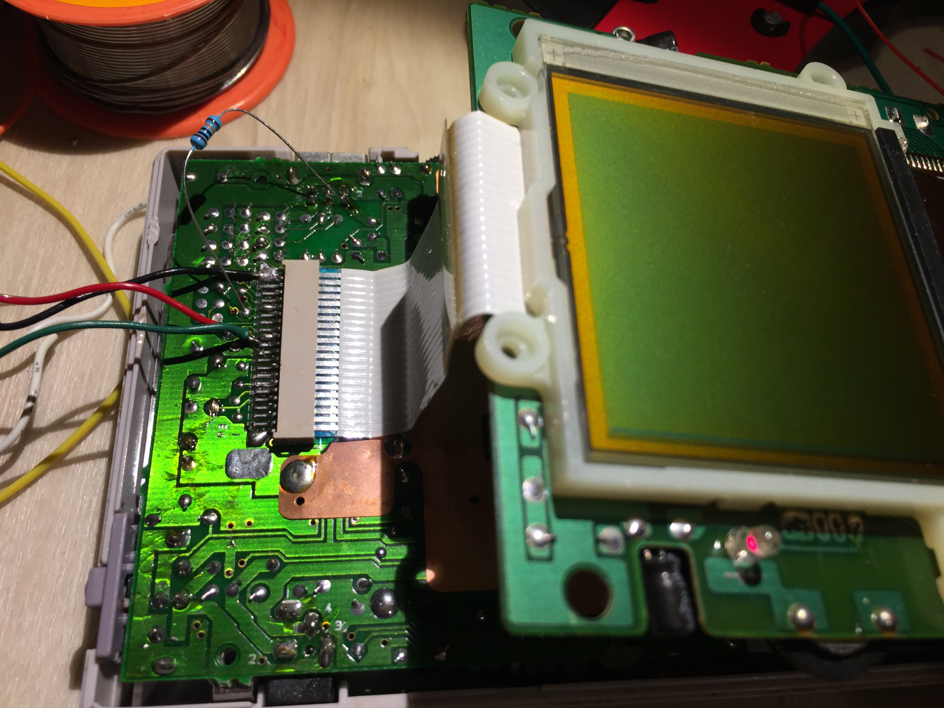
EDIT 2:
Here's a shot:
https://abload.de/img/img_75031ots20.jpg
Was i supposed to check VAC between the resistors ends, cause if not and it was supposed to be from HSYNC side to Ground, then sadly it's 0 on DC and AC:(
0VDC and 0VAC from the pin to ground after you added the resistor to +5V?
But ... you also said the voltage just across the resistor was also 0VDC? You must have wired that somehow wrong.
Yeah it's 0 on both voltages from pin to ground.
And there's no DC voltage if i touch each end of the resistor either, but there's a AC voltage.
Will recheck so i am not lying lol
EDIT:
Okay was lying haha, there is about 4.57 DC voltage across the resistor,
no clue why i didn't get that before, must have done something wrong and though i did it.
EDIT 2:
But confirmed that Pin to Ground is Always 0.
I think that sounds promising?
this logic analyzer trace shows that HSYNC is low for ≈90% of the time, so getting 4.5Vdc on average and any non-0 Vac would be not inconsistent...
Do you get a valid signal if you measure the HSYNC pin with the logic analyzer now that the resistor's in place?
Tried connecting from the Resistor (Pin side), but nothing comes up in the Logic Analyzer, with or without ground connected to it.
Can also note that the LCD itself doesn't work as before either.
This is the kind of situation I'd love to have an oscilloscope for. Even a crappy one...
You could try decreasing the resistor. Strict lower bound is 3kΩ, and I'd be uncomfortable below 10kΩ.
Hmm, doesn't seem to yield any difference on the LCD at 50k, 20k, 10k etc:(
