You're probably wondering how I managed to do something like this, but I want to give some background so I don't feel like a total idiot.  (This actually happened over two weeks ago, but I couldn't post then and forgot about it until now.) In my "honor's" physics class at my high school, our last assignment was a Rube Goldberg machine that had a bunch of aesthetic requirements, (don't know why; not even related to physics) including having a "theme" (we chose Tetris; barely any artwork) and having to make a sound at some point (I figured I would get music from the Gameboy game). Everyone was struggling to figure out how to make a noise with anything, but I knew I could have two wires going to the back of the Gameboy in the battery compartment for one battery and have one other wire going to each contact for the other battery and have the Gameboy on and the volume up, to where I could make it turn on remotely. (A lot of people ended up using birthday cards; I over-engineer everything...) I did that, and it worked fine; however, my teacher wanted it to get to the title screen music and not just the jingle, which meant I had to put it toward the beginning of the machine for it to play in time, and with how late in the project it was, I ended up having it share power with a motor, which worked perfectly fine. However, We later needed another motor, and that also worked fine, but we only got to test it twice before a member of my group took it home with him (and must have screwed up the sensitive wiring when he continued working on it). The next day, the sound was supposed to work, but when we tried to show it to the teacher, the Gameboy miraculously wouldn't turn on, which she said was because it "wasn't getting enough power". She told us two use two more AAs in a series and it would work, which I knew right away was a very shitty idea but class was ending and we would have gotten a failing grade, so I tried it, and it must have been enough electricity to jump the loose connection I later found because the translucent purple Gameboy Color turned orange in the battery compartment.
  Obviously, I unhooked it a millisecond after it happened, but it already smelt like burnt ass and knew it was probably dead, which it was. Surprisingly, there is no obvious damage visible and the game inside (Tetris) actually still works, which is why I wonder how extensive the damage is. (This should be apparent to you people, but I really don't know anything about electricity... At least I have four other Gameboy Colors. )
I don't think it's hopeless, but I can't say for sure. I don't know the GBC hardware at all, but battery-powered electronics (beyond the simplest cheap stuff) often would have a regulator in there. If the power supply isn't built out of custom parts, you could replace those if the damage was limited to those parts. I doubt the CPU etc. was directly connected to the battery.
I'm definitely a newbie when it comes to magnetics (I'm just now for the first time building a circuit that uses some inductors), but my uh-oh moment when reading that post was when you said the GBC was sharing the power supply with a motor. I know just enough to be a little dangerous, but what I do know is that a motor running backwards is a generator. And that powering an electromagnet will build up a magnetic field. When you remove the power, that magnetic field will collapse, and that power will have to go somewhere. That should be directed somewhere safe with a diode (look up "back-emf diode" or something). If there was no protection, the GBC power supply was probably not very happy to see this.
I'm definitely a newbie when it comes to magnetics (I'm just now for the first time building a circuit that uses some inductors), but my uh-oh moment when reading that post was when you said the GBC was sharing the power supply with a motor. I know just enough to be a little dangerous, but what I do know is that a motor running backwards is a generator. And that powering an electromagnet will build up a magnetic field. When you remove the power, that magnetic field will collapse, and that power will have to go somewhere. That should be directed somewhere safe with a diode (look up "back-emf diode" or something). If there was no protection, the GBC power supply was probably not very happy to see this.
Back EMF is a serious problem, controlling a relay or motor without a protection diode is asking for trouble, the pulses reach tens or even hundreds of volts, depending on the inductance of part in question.
Memblers wrote:
my uh-oh moment when reading that post was when you said the GBC was sharing the power supply with a motor. I know just enough to be a little dangerous, but what I do know is that a motor running backwards is a generator. And that powering an electromagnet will build up a magnetic field. When you remove the power, that magnetic field will collapse, and that power will have to go somewhere. That should be directed somewhere safe with a diode (look up "back-emf diode" or something). If there was no protection, the GBC power supply was probably not very happy to see this.
Sharing it with two 3V motors...
Thanks for the information though.
Espozo wrote:
The Gameboy Color, like the other Gameboys, uses these annoying tri-wing screws (probably so people can't easily open it)
A suitably sized flat-head precision screwdriver from the dollar store fits into two of the three wings of Game Boy and Nintendo DS tri-wing screw heads. Want a photo?
Yes.
A while ago you could find really cheap replacement GBC cases on eBay that came with tri-wing screwdrivers.
Somebody asked for pictures.
I thought I had a screwdriver that small, but I couldn't find it. I'm going to get some stuff from eBay anyway, so I'll just buy a tri-wing screwdriver.
Didn't take to long to figure out what failed.
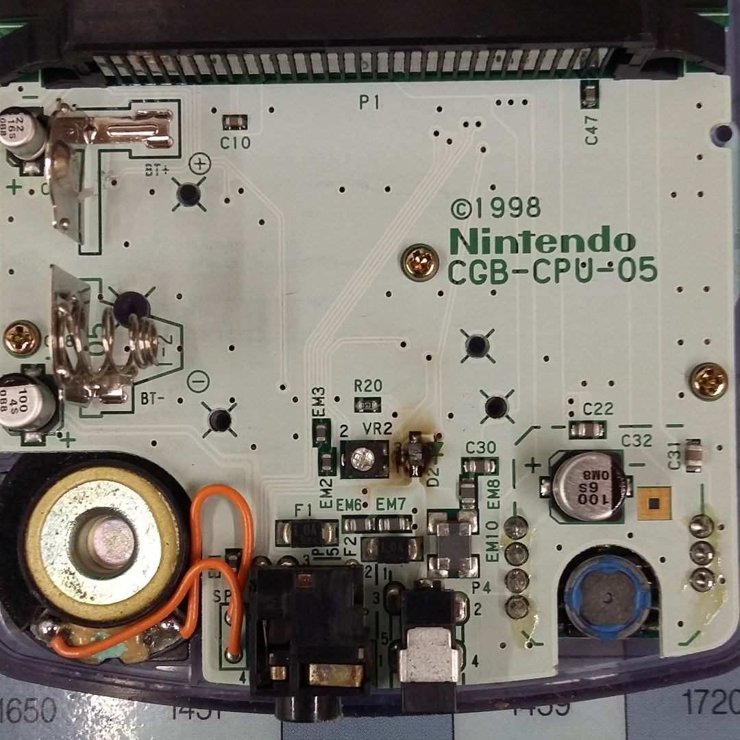
Inside Gameboy Color.png [ 1.8 MiB | Viewed 2542 times ]
It appears to say "D2+" on the right side, and "3-" on the left.
Attachment:
Inside Gameboy Color.png [ 1.8 MiB | Viewed 2542 times ]
It appears to say "D2+" on the right side, and "3-" on the left.
You blew up a diode. ("D"2)
It might be a zener diode ... ordinary (i.e. "not zener") diodes aren't usually what eats it when something is overvoltaged.
(Hunts down a schematic) Oh. That's a reverse-polarity protection diode instead. Part # is "1SS355".
(Hunts down a schematic) Oh. That's a reverse-polarity protection diode instead. Part # is "1SS355".
Thanks a lot.  It looks like I can purchase one from here: https://www.digikey.com/product-detail/ ... ND/3774962
Random caveats:
#1- you'll pay a significant overhead for shipping if you get it from digikey. (try comparison shopping using octopart and/or findchips)
#2 - do you have access to the right soldering equipment?
#3 - something else may have broken also. Try just desoldering the diode altogether and see if it works before you invest in a replacement.
lidnariq wrote:
do you have access to the right soldering equipment?
Yes.
lidnariq wrote:
something else may have broken also. Try just desoldering the diode altogether and see if it works before you invest in a replacement.
How should I connect both ends in the meantime?
The diode is there to protect later parts from negative voltages—if you don't connect a negative voltage it shouldn't matter. (Normally the diode shouldn't conduct, so a missing diode will never conduct) Obviously you want to put it later, but for (careful!) testing it's ok.
If you'd used the external DC power jack, the fuse F2 would have blown instead of the diode. But for some reason, the battery contacts are unfused against reverse polarity.
Hopefully the fuse F1 will have protected the DC/DC (boost) converter U5, but...
If you'd used the external DC power jack, the fuse F2 would have blown instead of the diode. But for some reason, the battery contacts are unfused against reverse polarity.
Hopefully the fuse F1 will have protected the DC/DC (boost) converter U5, but...
Quote:
#1- you'll pay a significant overhead for shipping if you get it from digikey.
Digikey has free shipping if you mail them a check.
I went to try and remove the diode, so I took the other side of the case off of the board, but there were no solder balls or anything, which doesn't really surprise me. However, I poked it with a screwdriver, and it was so fried it disintegrated. Unfortunately, I can't even see how it was originally connected because the board there is so burnt. Could I just put two solder balls on each side, then press the new diode on? I didn't get to test to see if the Gameboy Color works yet.
Just do a continuity meter between the two pads. If it's not conductive, then it's not conductive.
On the other hand, if the PCB is substantially burnt, you might need to check if any other traces are damaged.
On the other hand, if the PCB is substantially burnt, you might need to check if any other traces are damaged.
Uh, a bit of an update (sort of), but even without the diode in place, it still doesn't work. Something I'd like to have explained to me, is how is this supposed to work without the diode? I'm confused as to how electricity passing through the diode causes the Gameboy not to work. (I know I have much less knowledge about electricity than most people here.)
Espozo wrote:
Uh, a bit of an update (sort of), but even without the diode in place, it still doesn't work.
Unfortunately, that means that the diode is "merely" collateral damage, not the reason it's not working.The next most likely culpable victim is the voltage regulator (boost converter) U5. It supposedly takes the 3V from the batteries, and boosts it to 5V, -15V, and 13.6V. The only other things that I see connected to the unregulated battery voltage is the power LED D4 (does it still light when you turn it on? The power LED should light as long as both battery voltage and 5V is present and the battery voltage is high enough.)
Quote:
Something I'd like to have explained to me, is how is this supposed to work without the diode?
The diode is there to protect the rest of the circuit against a negative voltage. Normally it shouldn't be doing anything.However, now that it's burned up, if it is doing something, then it's shorting out the batteries. Hence no power could get to the voltage regulator.
You can test most of the game boy carefully using a 5V regulated power supply, and powering the 5V section manually (bypass the voltage regulator). I'm not sure if you'd hear sound in this case, but you'd at least be able to look for wiggling address lines on the cartridge connector.
Oh, there's the other part that I couldn't find that runs directly off the battery voltage: the audio amplifier IC.
As far as I can tell, the CPU should only need the 5V and 3V rails to be good (there's an LDO regulator deriving 3.3V from the 5V rail: U7/"RN5RT33A")
The LCD should be the only part that needs all 3 voltage rails.
(It wasn't hard for me to find the schematic. Just search for "gameboy_color_service_manual.pdf". )
lidnariq wrote:
Oh, there's the other part that I couldn't find that runs directly off the battery voltage: the audio amplifier IC.
As far as I can tell, the CPU should only need the 5V and 3V rails to be good (there's an LDO regulator deriving 3.3V from the 5V rail: U7/"RN5RT33A")
The LCD should be the only part that needs all 3 voltage rails.
(It wasn't hard for me to find the schematic. Just search for "gameboy_color_service_manual.pdf". )
As far as I can tell, the CPU should only need the 5V and 3V rails to be good (there's an LDO regulator deriving 3.3V from the 5V rail: U7/"RN5RT33A")
The LCD should be the only part that needs all 3 voltage rails.
(It wasn't hard for me to find the schematic. Just search for "gameboy_color_service_manual.pdf". )
I don't think the 3V rail is used at all by the logic, what is it used for?
Good question. It is connected to the package, though. 3V is supposedly also used by the SRAM inside the GBC, so maybe it's just for interfacing to that?