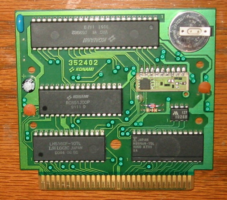
Wellll, as the topic says, I unpotted the hybrid in the VRC7. As I suspected, it was nothing too earth shattering.
I removed the epoxy, then removed the 3 caps and the op-amp and then read off the resistors and drew a schematic. There's absolutely nothing special about it.
http://blog.kevtris.org/blogfiles/vrc7% ... ematic.png
Some people might wonder what the 910 ohm resistor does on the output to ground. Since this is an LM358 basically, the output is crappy, so the resistor keeps the amp in class A and thus, there is no crossover distortion.
R4 and R5 form a negative feedback gain configuration, and C2 is an "AC ground" capacitor that cheats and lets you run the circuit from a single supply. The capacitor will have a voltage of approximately 1/2 supply when audio is present.
R1 converts the current output of the VRC7 into a voltage, and then R2, R3, and C1 perform some basic low pass filtering action.
R7 and R8 mix the two audio sources (fami audio and VRC7 audio) and then out it goes to the famicom.
The other op-amp isn't used and both inputs are tied to VCC.