Hello!
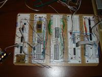
I build a nes-on-a-proto-board. In fact, it is more like a Famicom. It looks like:
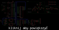
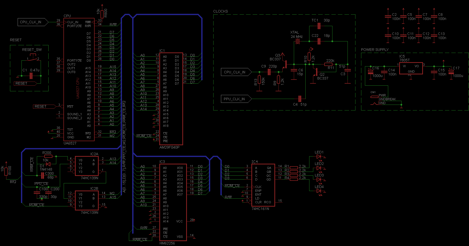
Bellow is a schematics.
There are also PPU and its ROM and RAM on the protoboard,
but they re isolated from the CPU at the moment, I am goin to make the CPU working at
first, so don't care about them.
Basically it consists of a UA6527P CPU (found in many famiclones),
29F040 512KB Flash-ROM and HM62256 32KB Static-RAM.
The 74HC139 address decoder (connected in the same manner like in Famicom)
generates enable signals for RAM and ROM (upon A13-A15 and M2 lines).
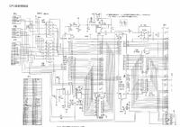
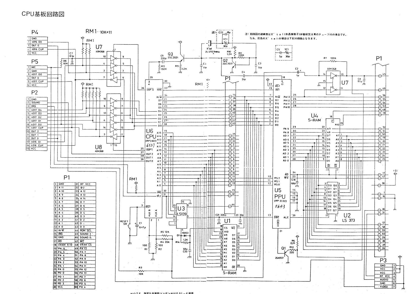
Everythin is based on this popular famicom schematics:
I added a 74HC161 latch (found in UNROM/CNROM/ANROM cartridges) which
latches lower 4 bits od data, stored at 8000-FFFF address. Four LED diodes
are driven by its outputs, so that they shows what data was latched.
So for example, when a
lda #%1010
sta $8000
opcodes are executed, LED2 and LED4 should be turned on and LED1 and LED3 off.
The RAM !CE line is connected with a capacitor-diode-resistor circuit, same like in
popular famicom schematics.
I guess it was done to delay the high to low (or low to high, I dunno) transision
of this line.
The clock generating circuit is also the same like in the popular famicom schematics.
The crystal is 24 MHz.
There are couple of 100n capacitors, connected close to the ICs to eliminate the noise.
Everything is powered with a 7805 regulator (with huge 1000u electrolic capacitors at input and output).
The 7805 is driven with a 9v DC supply from transformer.
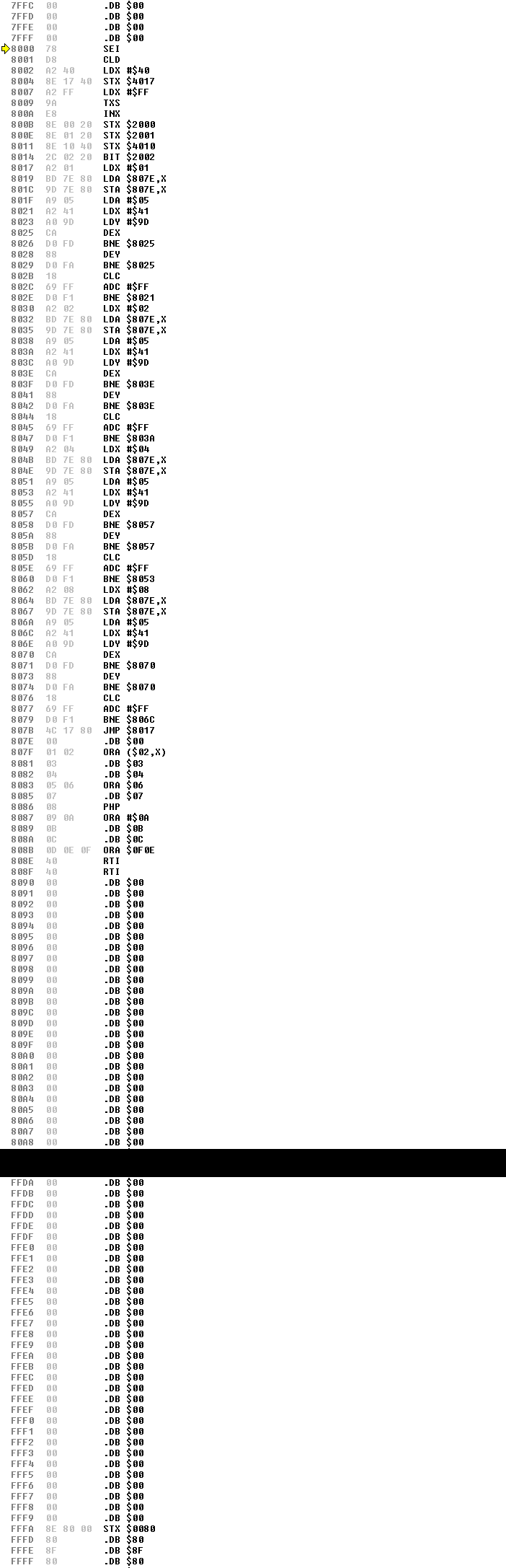
I wrote a simple ASM program, which should ligh the diodes in a sequence
LED1 LED2 LED3 LED4
1 0 0 0
0 1 0 0
0 0 1 0
0 0 0 1
with a few second delay between them. Then I compiled it to a 32768 binary file
and written on on 29F040 flash ROM (and I examined its contents - every byte is written correctly).
The vector handlers adresses are also correct.
http://students.mimuw.edu.pl/~krzysioba ... rd-rom.zip
However the problem is that the leds aren't blinking as I wanted - they behave
quite randomly, blink fast for a fraction of a second and then they froze.
The program does not even use the RAM.
The connections on the protoboard were rechecked ten times, with a multimeter.
Everything is like on the schematics.
So my question is why this is not working Have I missed something? I think the sound and
joypad extension ports on the CPU can be left floating, if not used.
I build a nes-on-a-proto-board. In fact, it is more like a Famicom. It looks like:

Bellow is a schematics.
There are also PPU and its ROM and RAM on the protoboard,
but they re isolated from the CPU at the moment, I am goin to make the CPU working at
first, so don't care about them.
Basically it consists of a UA6527P CPU (found in many famiclones),
29F040 512KB Flash-ROM and HM62256 32KB Static-RAM.
The 74HC139 address decoder (connected in the same manner like in Famicom)
generates enable signals for RAM and ROM (upon A13-A15 and M2 lines).
Everythin is based on this popular famicom schematics:
I added a 74HC161 latch (found in UNROM/CNROM/ANROM cartridges) which
latches lower 4 bits od data, stored at 8000-FFFF address. Four LED diodes
are driven by its outputs, so that they shows what data was latched.
So for example, when a
lda #%1010
sta $8000
opcodes are executed, LED2 and LED4 should be turned on and LED1 and LED3 off.
The RAM !CE line is connected with a capacitor-diode-resistor circuit, same like in
popular famicom schematics.
I guess it was done to delay the high to low (or low to high, I dunno) transision
of this line.
The clock generating circuit is also the same like in the popular famicom schematics.
The crystal is 24 MHz.
There are couple of 100n capacitors, connected close to the ICs to eliminate the noise.
Everything is powered with a 7805 regulator (with huge 1000u electrolic capacitors at input and output).
The 7805 is driven with a 9v DC supply from transformer.
I wrote a simple ASM program, which should ligh the diodes in a sequence
LED1 LED2 LED3 LED4
1 0 0 0
0 1 0 0
0 0 1 0
0 0 0 1
with a few second delay between them. Then I compiled it to a 32768 binary file
and written on on 29F040 flash ROM (and I examined its contents - every byte is written correctly).
The vector handlers adresses are also correct.
http://students.mimuw.edu.pl/~krzysioba ... rd-rom.zip
However the problem is that the leds aren't blinking as I wanted - they behave
quite randomly, blink fast for a fraction of a second and then they froze.
The program does not even use the RAM.
The connections on the protoboard were rechecked ten times, with a multimeter.
Everything is like on the schematics.
So my question is why this is not working
joypad extension ports on the CPU can be left floating, if not used.