Tl:dr
Every single script on Kazzo that I've tried has failed to dump CheetahMen: The Creation, properly.
I've attached a picture here showing an example; the sprites are garbaged, but the game itself runs totally fine. I've tested this cart on real NES hardware and the graphics are in tact, so it must have something to do with the script.
The only problem is: I have literally no idea how Kazzo scripts work, there is no way to know how exactly what to put in.
I know only one person who knows how to write scripts, and they unfortunately refuse to work with me on it due to stubbornness, so I've decided to come here and see if anyone can help me here.
Are these true Kazzo scripts, or INL's modern successor? If the former, what script did you use to generate this dump?
I think these are real Kazzo scripts, as I bought this device back before it was discontinued, I have used quite a few scripts including the standard nrom.ad.
I could not find pictures of this game's PCB, only butter hoarders demonstrating that they own the cartridge or selling it for ridiculous sums of money. This does not help with dumping.
Images like this also do not help. The board is not listed in BootGod's DB.
Start by providing high resolution pictures of both sides of the cartridge PCB (read: you must open the cartridge, it is not transparent enough to get clear visibility). The higher res the better. This will help disclose what the mapper chip is that's used, in addition to PRG and/or CHR size, as well as provide detailed traces for analysis. A hardware-oriented person here can likely figure out via the traces what likely existing script can be used, or which one can be modified (and in what way).
koitsu wrote:
I could not find pictures of this game's PCB, only butter hoarders demonstrating that they own the cartridge or selling it for ridiculous sums of money. This does not help with dumping.
Images like this also do not help. The board is not listed in BootGod's DB.
Start by providing high resolution pictures of both sides of the cartridge PCB (read: you must open the cartridge, it is not transparent enough to get clear visibility). The higher res the better. This will help disclose what the mapper chip is that's used, in addition to PRG and/or CHR size, as well as provide detailed traces for analysis. A hardware-oriented person here can likely figure out via the traces what likely existing script can be used, or which one can be modified (and in what way).
Ah, I probably should have posted the images here. Yeah I took some pictures of the PCB a week ago.


With that PCB, a 74LS377, 64K of PRG, and 32K of CHR, this might be mapper 11, 66, or 79 148. Probably not mapper 232.
I tried dumping it with all 3 of those mappers by clicking "change mapper", it still doesn't work.
Is there a specific script I need to use? My current script is "nrom_GUI.ad"
"nrom" implies you're just dumping it as NROM, period. With the Kazzo, you need separate scripts for each board. You should end up with a file that's 96KB in size, not 40KB.
If you have a multimeter, the best thing to do would be to figure out what pins on the ROM go to what pin on the 74'377. From that we can definitively tell you what the resultant hardware is.
74'377? Which chip are you talking about?
The smaller chip on the top right (look for the "377" printed on the top in the middle of some other letters and numbers). It should have 8 pins that connect to the card edge connector, and another 8 pins that connect to pins on the 2 ROM chips (the two bigger ones).
If you can determine which is connected to which, this mapper can be completely described.
An additional photo of the back of the board might get us halfway there, but for traces that go underneath chips and can't be seen, a multimeter can be used to check what's really connected.
This is what you want, right? I do not have a multimeter on hand right now. Is it absolutely mandatory to get one?
The 1st picture in the above reply is of the area of the board behind the CIC chip. That isn't particularly helpful (see last paragraph of this post), but the right hand side of the picture does depict some of the other traces (which ARE relevant), but because we can't see the rest of the board in the same shot, we can't tell what they're connected to.
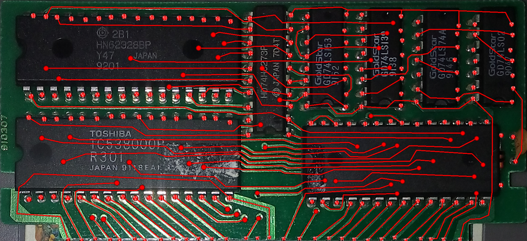
Because you don't seem to understand what's on the board, let's go over it using
this picture as a reference
1) 8-pin square chip below the "NTSC ONLY" silkscreening: this is the CIC lockout chip, probably RetroUSB's CICLONE chip (CIC clone). This is needed to comply with Nintendo's lockout protection; Google "NES CIC" if you care. Nothing special/magical about this chip
2) 28-pin rectangular chip to the right of the CIC chip: this is the CHR-ROM (i.e. graphics). It's an Atmel AT-27C256R DIP EPROM, 256kbits (32KBytes)
3) 28-pin rectangular chip to the right of the CHR-ROM: this is the PRG-ROM (i.e. code). I cannot read the silkscreening due to angle/lighting, but I suspect it is an Atmel AT-27C512R DIP EPROM, 512kbits (64KBytes)
4) 20-pin rectangular chip above the PRG-ROM: this is the mapper chip used for CHR-ROM and PRG-ROM bank switching, and possibly other features (unknown).. The silkscreening is again hard to read for the same reason, but I can make out "LS377H" just barely, I think, which means it's likely a 74LS377.
5) There is a solder bridge (solder dot) across the HORIZ pads, rather than VERT. That means it either uses horizontal mirroring (a.k.a. vertical layout) or possibly horizontal layout (a.k.a. vertical mirroring), for how the NES organises its video memory for multiple screens of data. I suspect it means Horizontal Layout, because
this video of the game depicts a horizontally scrolling game, not vertical.
This PCB in general looks to be a variant of
a Sealie Computing (RetroUSB) RetroPak board. Maybe "CD" is "Custom Design"? Don't know. bunnyboy, the guy who owns/runs RetroUSB, would probably be glad to help if we asked him. Not sure we need to, however.
Anyway, from (2), (3), and (4), we can tell definitively this is not an NROM game -- NROM games (a.k.a. "mapper 0") have no mapper chip, and are usually 32KB PRG + 8KB CHR because that's all the NES can address natively without a mapper chip**.
Gyromite is an example of an NROM game (the board there has 3 chips only: CIC + PRG + CHR). Hopefully now you understand why lidnariq said your dump should be 96KB (64KB PRG, 32KB CHR).
The 2nd picture in your reply; it is semi-blurry (mobile phones, sigh), but I think it might be good enough. I'll let lidnariq/others decide. But:
What we need is very clear photos of the board PCB (read: all the traces or "lines" that go from X to Y, especially from the edge/cart connector onward). It's hard because the PCB is blue, I know. As I stated originally, both sides of the board need very high resolution pictures. The ones you've provided so far have been so-so; the reference picture I mentioned above is actually the best of the bunch ((for seeing traces, etc.). You may have to take 20-30 pictures, with and without a flash, or even put the PCB inside of a scanner (if you have one) to see if you can get 1 or 2 really good results at the highest resolution possible. It may take multiple shots, which is OK. Here are some example threads which should give you some idea of the resolution and clarity needed, and what exactly the hardware folks do with these pictures:
viewtopic.php?f=9&t=19017viewtopic.php?p=236113#p236113viewtopic.php?f=9&t=18375viewtopic.php?p=228739#p228739 (great example)
It is from these pictures that hardware folks reverse-engineer the "setup" of the board and what chips are connected to what pins (or other chips) on the cart/edge connector -- and all of this is what the Kazzo dump scripts effectively need to know for a cartridge to be dumped properly. Without the proper script/configuration, the dump may be incorrect (garbled graphics, does nothing, crashes, is too large (overdump), is too small (underdump), etc.).
When it comes to dumping a game that hasn't been dumped before, it's very important you try to get it right -- multiple dumps are often needed (to verify/validate/ensure the bytes are consistently correct; bad dumps are VERY common! There's literally hundreds if not thousands). But the first step is understanding the board config, then writing the Kazzo script that should work with it, seeing if you got the right filesize, and/or possibly writing or modifying the 16-byte NES header that correctly matches the board setup (maybe Kazzo does this for you, not sure), then trying the ROM in an emulator and playing it as far as possible (and doing the same on real hardware) to make sure nothing is missing/mangled.
Does this make more sense to you now? :-)
** -- Pedants, do not get fixated on this statement. You know exactly what I'm conveying to the OP here.
The photos I've shown are pretty much the absolute best I can take using my limited camera resources, so instead I can read the 20 pin chip to you.
07D51VK E4
SN74LS377N
I guess what I can do with the traces is I can open it in Paint.net and put some colored lines on the traces to show where they all lead, is that a good solution?
I'll let lidnariq/others decide. The reference picture you took of the front of the board is really good, it's totally usable. The rear board picture may be good enough; there aren't a huge number of traces, which make this a bit easier.
Thanks for the mapper chip ID; yeah, that's a classic flip-flop and
is most certainly used in some other boards.
The thing is: sometimes PCBs can wire things up (from edge connector to chip or pin) differently than other boards, so that's why PCB pictures are needed. The wiring is what depicts what memory/address ranges control the mapper. I'm not a hardware guy, as much as my earlier description might make you think otherwise.
I'm ~99% certain lidnariq is familiar with this chip and it shouldn't pose too many problems. I suspect it's similar, if not identical, to some of the Color Dreams boards/games. Mapper 11 might be a good starting point. If the board varies compared to "standard" Colour Dreams games, then the PCB pictures should help tell us that. After that, it's a matter of finding or writing a mapper 11 (or whatever mapper) Kazzo script.
Just wait for lidnariq et al to provide some answers.
P.S. -- For Tepples/Memblers: can we have this thread moved from Newbie Help Centre to NES Hardware and Flash Equipment? I suspect krzysiobal could help too, if needed. Edit: looks like lidnariq is active on the forum, so maybe not necessary. :)
I can't really tell from the pictures. Too many traces are hidden under the ICs to make educated guesses about what's connected where.
If ShadowMan44 is willing to use a multimeter (or a cheapo homebrew continuity meter) to determine which pins from the 74LS377 go to what pins on the ROMs, we could tell you which script is needed to use to dump it (or I could write one).
Otherwise ... I have no better idea than just trying a bunch of different scripts and seeing what works. (Does the CNROM script produce 32KIB of CHR? Does the ANROM script produce 64KiB of PRG?)
Alright, I didn't want to go into the garage but I guess I have no choice but to get my device out, I can't guarantee that my statements will be accurate.
EDIT:
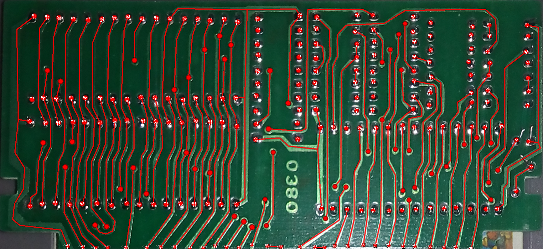
I've got my multimeter out and I've made colored lines over what traces made beeps when I put them together. Again I can't guarantee what I've done here is accurate.
lidnariq was stating that what needs to be traced out via multimetre continuity tests are on the *front* of the board, especially the traces that go under ICs (i.e. stuff we cannot see from photos). The back of the board tends to be pretty basic/simple on most cart PCBs (but both sides are important given how often through-holes are present). What goes where from the cart/edge connectors is really what's most important for starters, since a lot is pass through via the NES to the edge connector.
So, if you can do something similar for the front of the PCB, esp. tracing where the edge connector pins go trace-wise --
exactly like you see depicted here (but using different colours helps!) -- then that would be super awesome.
Otherwise, I can try to track down/summon bunnyboy and see if he can just provide a schematic or what not since he probably has it for that board. :)
koitsu wrote:
lidnariq was stating that what needs to be traced out via multimetre continuity tests are on the *front* of the board, especially the traces that go under ICs (i.e. stuff we cannot see from photos). The back of the board tends to be pretty basic/simple on most cart PCBs (but both sides are important given how often through-holes are present). What goes where from the cart/edge connectors is really what's most important for starters, since a lot is pass through via the NES to the edge connector.
So, if you can do something similar for the front of the PCB, esp. tracing where the edge connector pins go trace-wise --
exactly like you see depicted here (but using different colours helps!) -- then that would be super awesome.
Otherwise, I can try to track down/summon bunnyboy and see if he can just provide a schematic or what not since he probably has it for that board.

I think getting "bunnyboy" is probably the best solution, I don't really understand any of these instructions so this may be the trump card at this point.
The instructions are pretty simple: you use your multimetre's continuity test to figure out what the cartridge edge connectors (pins) connect to on the front and back of the PCB, by following the traces from the pins to wherever they end up. Some should be pretty obvious cuz you can see the traces from start to finish, like you did with part of the back of the PCB (those look fine!). But now do the same for the front of the PCB, for all the cart connector pins on that side.
The ones that are particularly important to us are the traces that go underneath an IC (like PRG or CHR) -- we can't tell where they go visually, and you probably can't either, but your MM continuity test can. You just put one probe on one of the pins that has a trace that goes under the IC, then "poke around" where you think the trace might go (it's usually nearby where it disappears); for example, it might go to one of the pins on the PRG chip, or the CHR chip, or even the 74377. In some cases, the pin may even go to multiple places. Do each pin at a time, and draw it out like you did with the back of the PCB (in a unique colour). Some pins may not go anywhere (i.e. probably go to an entire grounding plane), so they may end up appearing connected to other pins, some pins on ICs, etc. (that's normal for a grounding plane).
You cannot hurt the PCB/game doing any of this since the cart isn't in the NES when you're doing it (read: no voltage flowing across the board), if that's what you're worried about. Just don't scratch the PCB/traces is all.
If this is still too much for you, then I'm not sure what to really tell you. You're in possession of something that you wish to dump, but nobody seems to have a dump of it**, so you have to do the work to get to the point where others can help you make a Kazzo script so it *can* be dumped. My money is on mapper 11, but we don't know for sure. Anyway, your options are, as I see it:
1) Do what's described here,
2) Send the cartridge to someone else who can do it -- either the trace work, or the dumping, or both (I dumped Twin Eagle back in the late 90s) -- who is trustworthy/won't screw you over/give you the ROM/will send the cart back to you,
3) Hope someone else has already done it and comes forth with information,
4) Try to reach out to bunnyboy/Brian and see if he can provide PCB schematic/details, since he's likely the inventor.
5) Give up on trying to dump it.
bunnyboy is very busy (family + full-time job), so there's zero guarantee as to when he'd respond (ex. it's been several years since I talked when he invited me up to his place to visit). If potentially waiting forever is OK with you, then that's fine too. It's all up to you. There's no wrong choice, IMO!
No insult intended, but I'm really not sure what you were expecting. You didn't think dumping undumped NES carts would be some "magic automated process" where you just bought a dumper, shoved a cart in, ran a program, and clicked a button, did you? If this was an official Nintendo PCB and official game, it'd be a lot easier (esp. if there was already a Kazzo script for that particular PCB), but it's third-party and doesn't appear to have been dumped before**.
For (1), if you want someone to make you a short video on YouTube demonstrating how to do it, I could probably put together something quick this weekend demonstrating it with an actual cartridge (I have an MMC3/Legacy of the Wizard cart around here somewhere...). It's really not that hard, and doesn't take *too* long using a combination of a good PCB photo + a graphics editor.
If the reverse engineering was more complicated, such as something more than continuity tests (voltage, resistance, and anything requiring the cart be actively powered while being RE'd), I would just have someone else do it. I'm a smart guy, but not particularly smart in those ways.
** -- I suspect someone does have a dump of it, just that it hasn't been released probably out of concern for piracy. The PRG and CHR are EPROMs, not mask ROMs, which means someone bought a RetroUSB board and programmed the ROMs from file(s). I can't believe any Action 52-esque game is worth $300 though. Crazy.
So what the instructions are is that, I put one needle on a single pin of the 377 chip, and then I try poking all the points on the rom chips to see if it'll make a sound indication there's connection? I'm totally lost here.
EDIT
This took many hours, a lot of sweat and a lot of back pain but I've tested all the connections, and did the "connect the dots" thing with the multimeter, here is the result.
ShadowMan44 wrote:
So what the instructions are is that, I put one needle on a single pin of the 377 chip, and then I try poking all the points on the rom chips to see if it'll make a sound indication there's connection?
Yes, exactly that.
I expect each one pin on the
74'377 will be connected to exactly one pin on
the ROMs.
lidnariq wrote:
ShadowMan44 wrote:
So what the instructions are is that, I put one needle on a single pin of the 377 chip, and then I try poking all the points on the rom chips to see if it'll make a sound indication there's connection?
Yes, exactly that.
I expect each one pin on the
74'377 will be connected to exactly one pin on
the ROMs.
The diagram I made shows that not all the pins connect to the rom chips, as some of them didn't show any sign of connectivity
You only found the easy pins - "D0" through "D7" (grey, magenta, cyan, lighter blue, xx, blue, gold, peach). While the connection from "Q4" (red) to CHR A13 does imply this is Color Dreams = mapper 11, I admit I was hoping for a little more. At the very least, CHR A14 (the pin between red and green on the left IC) and PRG A15 (the top left corner of the right IC) should be there too...
But you could try this:
https://github.com/arantius/anago-scrip ... pper_11.ad... oh, I bet "CD" means "Color Dreams"...
lidnariq wrote:
... oh, I bet "CD" means "Color Dreams"...
Oh god, I didn't even think of that. You're probably 100% right here. So yeah, it's probably mapper 11 or some subset of it.
Aaaaand it has the same issue that it's been having
How big is the resulting file?
lidnariq wrote:
How big is the resulting file?
I get 40KB, when you said it should be 96KB correct?
Did you download the file I linked to? Configure Anago or Unagi (whichever you're using) to use it?
lidnariq wrote:
Did you download the file I linked to? Configure Anago or Unagi (whichever you're using) to use it?
I saved the github script in txt, and renamed the file to an AD file, then loaded it into anago wx
Exactly as I've been doing all this time.
Does the Unagi output window say anything about "mirroring Program ROM fixed" or "mirroring Charcter ROM fixed" ?
lidnariq wrote:
Does the Unagi output window say anything about "mirroring Program ROM fixed" or "mirroring Charcter ROM fixed" ?
Yes, yes it does
mirroring Program ROM fixed
mirroring Charcter ROM fixed
C:\Documents and Settings\_________\Desktop\Cheetahboys.nes, mapper 11
Program ROM: size 0x008000, crc32 0xd11bfeb8
Charcter ROM: size 0x002000, crc32 0xc29016c2
Cheetahboys is just what I named the rom to test it

I don't know anything about how these scripts work (would have to learn), but 40KBytes probably means 32KB PRG + 8KB CHR (so probably per NES header, 2x PRG banks and 1x CHR banks).
From this it looks like
pagesize is being calculated wrong for both PRG and CHR. I suspect PRG count should be more like 4x16KB (i.e. 64KB total) and CHR count should be more like 4x (i.e. 32KB total).
Mapper 11 apparently uses 32KB PRG banks for swapping, so I suspect
pagesize for PRG is 1, and also 1 for CHR, hence erroneous 40KB result.
Otherwise there is something different about this PCB wiring vs. classic Color Dreams boards, which is certainly possible too.
How do we go about this then? Are we going to have to write a totally new script for this cartridge, do I have to do more with the multimeter?
Try starting with the
GNROM script and swapping the
cpu_write() lines at line 21 (in
cpu_dump()) and line 28 (in
ppu_dump()).
It's not surprisingly, the same result as before.
Just for curiosity's sake, what happens if you try using the "anrom.ad", "anrom_.ad", or "aorom.ad" scripts bundled with the kazzo source? Is the result 32KB, or does it become 64KB?
*edit* oh, and another thought: PM me the broken dump you have? Maybe the PRG ROM's output drivers are so strong that they meaningfully compete with the Atmega IC on the Kazzo, and we have to use different addresses to avoid a bus conflict?
lidnariq wrote:
*edit* oh, and another thought: PM me the broken dump you have? Maybe the PRG ROM's output drivers are so strong that they meaningfully compete with the Atmega IC on the Kazzo, and we have to use different addresses to avoid a bus conflict?
Ref:
Quote:
Some variations of this board/mapper (e.g the one used in the prototype game "Free Fall") appear to be free of bus conflicts and will not work properly if bus conflicts are emulated.
lidnariq wrote:
Just for curiosity's sake, what happens if you try using the "anrom.ad", "anrom_.ad", or "aorom.ad" scripts bundled with the kazzo source? Is the result 32KB, or does it become 64KB?
AN ERROR HAS OCCURED [the index 'ppu_rom' does not exist]
CALLSTACK
*FUNCTION [dump()] dumpcore.nut line [22]
LOCALS
[ppuarea_memory] NULL
[vram] 0
[increase_ppu] 1
[increase_cpu] 11
[mappernum] 7
[script] "anrom.ad"
[d] USERPOINTER
[this] TABLE
AN ERROR HAS OCCURED [script logical error]
CALLSTACK
*FUNCTION [dump()] dumpcore.nut line [47]
LOCALS
[ppu_dumpsize] 0
[cpu_dumpsize] 131072
[ppuarea_memory] 1
[vram] 1
[increase_ppu] 1
[increase_cpu] 1
[mappernum] 7
[script] "anrom_.ad"
[d] USERPOINTER
[this] TABLE
AN ERROR HAS OCCURED [the index 'ppu_rom' does not exist]
CALLSTACK
*FUNCTION [dump()] dumpcore.nut line [22]
LOCALS
[ppuarea_memory] NULL
[vram] 0
[increase_ppu] 1
[increase_cpu] 11
[mappernum] 7
[script] "aorom.ad"
[d] USERPOINTER
[this] TABLE
Try this:
Code:
board <- {
mappernum = 11,
cpu_rom = {
size_base = 0x10000, size_max = 1 * mega, banksize = 0x8000
},
ppu_rom = {
size_base = 0x8000, size_max = 1 * mega, banksize = 0x2000
},
ppu_ramfind = false, vram_mirrorfind = true
};
function cpu_dump(d, pagesize, banksize) {
for (local i = 0; i < pagesize; i += 1) {
cpu_write(d, 0x8000, 0);
cpu_write(d, 0x823C+i, i);
cpu_read(d, 0x8000, 0x4000);
cpu_read(d, 0xc000, 0x4000);
}
}
function ppu_dump(d, pagesize, banksize) {
for (local i = 0; i < pagesize; i += 1) {
cpu_write(d, 0x8000, 0);
cpu_write(d, 0xDFB6+i, i << 4);
ppu_read(d, 0, 0x2000);
}
}
There is a bus conflict prevention table, but it's not monotonic:
Attachment:
 cheetah-histogram.png [ 475 Bytes | Viewed 405 times ]
so I just elected to use other coincidental sequences instead.
The filename of the image sums it up perfectly.
At this point, I have no idea why it's not working. The hardware is
probably Color Dreams, but your continuity tests were inconclusive. There's no obvious way that the hardware could know if it were in a dumper instead of a console (the CIC isn't connected to anything else, M2 is unused), your dump of CHR looks plausible, and your dump of PRG gets as far as drawing a title screen.
The last time someone tried to dump a Color Dreams game they had
very similar problems.
For whatever reason, the latch is clearly not getting the value that the Kazzo is writing. I don't know why.
Do you have any random electrical components? LEDs, resistors, wires, alligator clips, headphones?
lidnariq wrote:
At this point, I have no idea why it's not working. The hardware is
probably Color Dreams, but your continuity tests were inconclusive. There's no obvious way that the hardware could know if it were in a dumper instead of a console (the CIC isn't connected to anything else, M2 is unused), your dump of CHR looks plausible, and your dump of PRG gets as far as drawing a title screen.
The last time someone tried to dump a Color Dreams game they had
very similar problems.
For whatever reason, the latch is clearly not getting the value that the Kazzo is writing. I don't know why.
Do you have any random electrical components? LEDs, resistors, wires, alligator clips, headphones?
What do you mean by this?
I need to clarify that the game despite the graphics being corrupted, the game itself runs fine.
I tested this game several times in my NES hardware, the graphics are fine.
ShadowMan44 wrote:
What do you mean by this?
I said too many different things for me to be able to usefully answer that question. You'll have to point at each specific thing you'd like me to re-explain.
ShadowMan44 wrote:
I need to clarify that the game despite the graphics being corrupted, the game itself runs fine.
Some games can run for a surprisingly long amount of time with only part of the PRG ROM. We can see that that's a 64KB ROM for PRG there, but you only have 32KB of it. At some point, part-way through the game, it's extremely likely it'll crash.
lidnariq wrote:
ShadowMan44 wrote:
What do you mean by this?
I said too many different things for me to be able to usefully answer that question. You'll have to point at each specific thing you'd like me to re-explain.
"Do you have any random electrical components? LEDs, resistors, wires, alligator clips, headphones?"
What do I need these for?
I believe the random electrical parts are meant for building a makeshift continuity testing rig. Quoting previous posts:
lidnariq wrote:
If ShadowMan44 is willing to use a multimeter (or a cheapo homebrew continuity meter) to determine which pins from the 74LS377 go to what pins on the ROMs
koitsu wrote:
The instructions are pretty simple: you use your multimetre's continuity test to figure out what the cartridge edge connectors (pins) connect to on the front and back of the PCB
[...]
The ones that are particularly important to us are the traces that go underneath an IC (like PRG or CHR) -- we can't tell where they go visually, and you probably can't either, but your MM continuity test can.
Why would I need to do that? I already have a multimeter, and I already have used it to make a diagram of the boards.
No, to detect what the output of the latch is. Ideally while dumping it, but maybe while running also.
lidnariq wrote:
No, to detect what the output of the latch is. Ideally while dumping it, but maybe while running also.
You mean I'd have to check the continuity of a circuit while the board is currently on? Isn't that dangerous?
That's why I was suggesting hooking up something with alligator clips. If there's no short when it's off, and you don't move things while it's on, it's safe.
Do I really have to do this?
Also, what is a "latch"?
No, you don't have to do this, but I have no idea why the script is not working, and I have no idea what else to try..... well, ok, you could try the AOROM script from
here, maybe. But I see no reason it'd work (i.e. result will be 32KB not 64KB) given that the designed-for-Color Dreams scripts haven't worked.
I'm not even certain how adding LEDs will help, so ... shrug.
The emulator doesn't even load the game up with that script, a waste of time to try it but I did it to make myself comfortable.
Maybe the reason why it isn't working is because someone needs to open a hex editor and hack it somehow...?
ShadowMan44 wrote:
The emulator doesn't even load the game up with that script, a waste of time to try it but I did it to make myself comfortable.
How big is the file. This is important. Is it still 32KB? Then it failed, and nothing has changed. Is it suddenly 64KB? Then
we've succeeded partway.
Nope, it is still 32.0k. At this point we've reached a dead end, none of the scripts we've tried work and there's no way to figure out what's causing the problem.
Respectfully I must disagree with your assessment (that this is at a "dead end" and "there's no way to figure out what's causing the problem"). I actually think what's being shown on-screen is just a garbled version of the actual initial power-on screen (ONE PLAYER, TWO PLAYER, MAIN MENU), but that's a gut feeling based on some anecdotal evidence in the screenshots compared to videos of the actual game/cart being played.
I'm of the opinion you're about a third or half way there, just that due to your lack of experience with any/all of this, you're frustrated. I can understand that frustration because low-level hardware pieces are not my forte either. But what's being asked of you isn't really low-level. For example, I can't really read a schematic well but I can build something if I'm given clear instructions or a VERY verbose schematic -- and I certainly can use a multimetre to create
something akin to
this purely via continuity tests, and without the cart needing to be powered. Other hardware-level analysis would require me to ask for a assistance, and if I did not feel comfortable doing it, I would ask someone with that experience for help, else to do it for me. I also believe part of your frustration lies in the fact that you're "coveting" this cartridge for some reason (I've seen people do this with all sorts of things, it's something I do not understand).
Other options were presented to you earlier in the thread by me. I made a menu of choices you had available as I saw them. They are all still valid options. You also obviously did not read what I wrote in full, because in one of the paragraphs I offered something that you did not respond to (hint: lidnariq saying "your continuity tests were inconclusive" -- well, you could rectify that! You're the one with the cartridge!).
You keep responding with short, terse, one-line responses -- as if you really don't have the time to spend on accomplishing the goal you wish to achieve. That's kind of narcissistic, and I say that without trying to start an argument (honest!). We're all trying to help you, but you're almost acting... I don't even know the words... voluntarily stupid? Maybe just extremely defeatist? I don't know. It's disappointing because we're all honestly capable of doing this, and we understand you aren't sure what you're doing, which is why we've tried to explain it (please see my previous paragraph again).
I believe you bought or got a Kazzo, then spent probably US$300+ on this cartridge, doing little-to-no research on what would be required of you to dump it (i.e. you thought it would be as easy as shoving a cart in, running a program, and magically get a ROM), or maybe someone somewhere on the Internet told you "it's easy bruh just buy this thing and click and type this command and you're done!". I don't know. What I do suspect is you're now in a lot deeper than you originally anticipated/expected.
It's also possible that the Kazzo isn't capable of working with this particular board type. lidnariq posted some evidence of people trying before on a real Color Dreams cart), or possibly it can work but there are nuances of the Kazzo not understood by some of us here. I for example do not have a Kazzo dumper, but I do have the latest INLretro Dumper/Programmer, which does not use anago/kazzo scripts but instead some Lua scripts. I'm familiar with Lua, and I have a good relationship with Paul from INL plus most of the folks here on the forum, so...
Re-visit earlier posts in the thread. As I said, you still have options.
What am I supposed to do, desolder all the chips so we can see what the board looks like on the inside!?!?!!?!?
ShadowMan44 wrote:
What am I supposed to do, desolder all the chips so we can see what the board looks like on the inside!?!?!!?!?
That would actually be very useful, though if all you've got is an ordinary soldering iron I'd only recommend doing that as a last resort, given the amount of work required (and the risk of damaging the board and/or chips in the process) - if you've got a quality desoldering station, I'd be wondering why you haven't done it already.
Also, as a side note (and echoing koitsu's previous message), expressing your frustration so vocally probably isn't going to make things much easier - just be patient and open to our suggestions and we'll be able to solve this problem.
Since I have no idea why the Kazzo isn't working, the next step I'd suggest would be desoldering only the 74LS377, and use jumpers to tie the three pins that go from it to the two ROMs high or low. Should be possible to dump the entire game in 4 passes in the Kazzo, since there are only two 32 KiB PRG banks and four 8 KiB CHR banks.
Let me just say something real quick
I have never desoldered a chip in my life, the most work I have done with soldering is replacing batteries in a Pokemon cartridge. I once tried to put new solder on a pin but the solder always stuck to the top of the pen and was pretty much impossible to put onto the board.
The other options "giving up, and sending the game off to someone else" are totally out of the question. I bought the game, I spent the money, I'm the one who will dump the rom, no matter the cost.
The reason why lidnariq suggested desoldering the 74377 is that it's a common and easily replaceable electronic component. Because you can just replace it, you can snip all its pins off and destroy it, which makes the desoldering process a lot easier.
The actual EPROMs have the valuable information, and are harder to desolder too because of their shape and large number of pins. That would be a more last last resort to suggest.
However, I'd be really surprised if this isn't exactly or almost exactly the mapper we already think it is. My most likely guess is some error is going on with the software, the scripts, or how they're being used on your computer, or something like that. I think it might be worth trying to troubleshoot that a bit more before trying hardware modifications. (Do other cart dumps work correctly with your setup?)
Finally, one thing I don't think has been mentioned is maybe check the remaining pins of the 74377 and see if they connect to any of the card edge pins of the PCB (the gold fingers on the edge, both sides). We would expect to see 6 specific pins connected to 6 specific edge connectors, but maybe they're in scrambled arrangment here?
rainwarrior wrote:
Finally, one thing I don't think has been mentioned is maybe check the remaining pins of the 74377 and see if they connect to any of the card edge pins of the PCB (the gold fingers on the edge, both sides).
He found that D0-D3 and D5-D7 were connected to the PRG ROM data lines; I'm comfortable saying that all eight lines are connected and in order despite D4's conspicuous absence.
Quote:
but maybe they're in scrambled arrangment here?
Not obviously. He found Q4 connects to CHR A13, and the few visible traces in the photo of the underside connect from Q5 to CHR A14 and Q6 to CHR A15. I can't say about Q0-Q3 or Q7.
The bad dump he sent me included the reset stub (
x: lda #$11 /
sta x+1 /
jmp $8009). The code at $8009 is a credible init routine, so I have to assume that this bad dump is of PRG bank 1, not PRG bank 0.
I have no idea why the Kazzo isn't working; this is pretty clearly the Color Dreams hardware. But as I linked earlier, a previous person trying to dump a Wisdom Tree game had similar problems.
A list with all twenty 74ls377 pins would be helpful, showing their function, and their connection to the cart edge or rom chips. Using colored dots for some random pins here and there instead of making a schematic isn't so professional. With that technique it's easy get lost, for example, 74ls377 pin1, is the connection already known, or was it even considered to be connected anywhere yet?
Btw how are dumping tools handling bus conflicts? Are they searching for matching rom bytes, and then write to that address? Or are they just writing by force, hoping to have more amps than the rom chip?
Ps. Using a multimeter works as so: Hold one probe to the pin that you are looking for, then slide the other probe across the cart edge contacts until it makes beep, that shouldn't take hours when searching for only 20 pins.
Just in case anyone reading this thread needs it, the wiki has pinout reference and other information for:
nocash wrote:
Btw how are dumping tools handling bus conflicts? Are they searching for matching rom bytes, and then write to that address? Or are they just writing by force, hoping to have more amps than the rom chip?
lidnariq's script posted above tried to position the writes exactly on a bus conflict table that appeared in the single-bank dump that I presume was shared privately.
When I wrote CopyNES dumping scripts for bus-conflict mappers I would have it search the ROM space for a matching byte. I dunno how easy that is to do with anago/kazzo though.
nocash wrote:
Btw how are dumping tools handling bus conflicts?
Kazzo scripts assume that the underlying Atmega16 wins all bus conflicts. Prior evidence has insinuated that it's true.
rainwarrior wrote:
I dunno how easy that is to do with anago/kazzo though.
Anago/Unagi don't obviously expose a way for the embedded SquirrelVM to programmatically read a byte and use its contents.
Ok. So from this post (
viewtopic.php?f=10&t=19093&start=15#p240720), it looks like CHR-A14 is hooked up to Q5, CHR-A15 (VPP) is connected to Q6, and /ROMSEL connects to CLK.
Also, /WE is hooked up to something. CPU R/W looks like it's in about the right place for that, and that would be expected for Color Dreams.
From this post (
viewtopic.php?f=10&t=19093&start=15#p240753), we also have D0=D0 through D7=D7 except for D4. That is almost certainly hooked up as well, as there is a trace headed that way.
We also have CHR-A13=Q4. It also sure looks like there is a trace connecting PRG-A15 with Q0.
If the /WE, D4, and Q0 are confirmed this is exactly Color Dreams with support for 64K PRG/CHR (does grounding the VPP line on the CHR-ROM matter? Would require using "| 0x40" if so). Q1, Q2, Q3, Q7 would be expected not connected in this case.
So what's going wrong? A couple of theories:
-First, I'd check the mirroring flag. I believe the Kazzo only tests/and sets the mirroring flag if the dumping scripts specifies this. It looks like vram_mirrorfind is set, so it should be ok, but it's worth checking). From the pictures posted, it looks like PPU-A10 is connected to CIRAM-A10, so vertical.
-Next, is it possible both banks of the PRG have the menu code in them? Maybe the version lidnariq has is using one bank (maybe dumped with NROM script?), but the version being dumped with his modded script is starting (after the 0 write 0x8000 or maybe after completing the script once) in the other bank. This would mean the ROM values he recommends might not match for the bank that's currently active, causing the bus conflicts to be causing issues.
My suggestion is to first check the mirroring flag. And my second suggestion is to make sure that CRCs match for the existing dumps. When dumping with the Kazzo, it always gives the CRCs of the PRG and CHR. Make sure to watch them. If two dumps have the same values, you don't need to test the new dump again as it will be the same. If they're different, however, they need to be examined closely.
He's not using an NROM script. He's using the Color Dreams scripts ... and also the AOROM script ... and it's the local GUI ("Unagi") that's saying "hey, I've got a file that clearly repeats over and over; there's only 32KB of PRG and 8KB of CHR here". The thing he sent me privately is this thing.
Somehow, the bankswitch writes aren't happening, or if they're happening the latch is immediately reverting to some constant value. The resistors and LEDs would help figure out which, but regardless it doesn't suggest a way forward to get a valid dump. Maybe it's a bug in the Kazzo firmware, but if so, why are Color Dreams PCBs the only mapper that gives us this trouble?
Overpowering the outputs of the latch would be a way forward, tying Q0, Q1, and Q4 to +5V or ground. I wouldn't want to do it long term, but doing this for long enough to run Unagi four times should be ok enough. And the only thing it might damage would be the 74HC377 anyway, which is a commodity part and replaceable without much cost.
Rhetorically, yes. But does the cart owner have a glimpse of an idea about pin numbers or pin names like Q0 or Q1? Currently it might be better to stick with colored dot language, like "wire green dot to purple dot", or whatever.
Or somebody take the time to make a list, I am surprised nobody did that yet, alike...
Code:
74LS377.pin1 (color this) (/WE) ------- unknown connection ????
74LS377.pin2 (color blah) (pin name) ------- cart.edge pinN (pin name)
etc.
Maybe that would help to clarify that the pins have actual functions, and that it is important to know where they connect to, and perhaps the question marks would motivate the cart owner to find out where the pin connects to. You know, like "oh, man, I had never thought about that pin! Haha. I will check that right now!"
On the software side, it is known how to map the PRG bank for the init/menu stuff. But is it also known how to map other (undumped) banks? If /WE connects somewhere to address bus then it might work only for certain addresses.
Are you guys sure it isn't possible to like romhack the game to make the graphics work?
Maybe what you have to do to get it to "look right" is change some values in the hex editor, unless the file size being inaccurate means that a lot of code was left out from the initial dump?
Dumping depends on wheter you answer open question. For that super simple board, I think that dumping isn't a problem technically, it's mainly a problem about communicating questions about pin connections to somebody who isn't experienced with such questions.
Instead of that... filling missing bits in a hex editor, if you want to rewrite the game from scratch up and then manually key in the code in a hex editor, yes of course that is possible, but is that really what you are up to?
Edit: Thinking about it, I guess 74ls377 pin1 connects to R/W on cart edge?
Edit2: If you were referring to the mirroring flag, yes that would be edited via hex editor.
Rewriting the entire game from scratch? I'd like to keep my sanity, thanks.
Is it possible that a different, more up to date NES dumping device would dump the game better? Kazzo devices have been out of date for about a year now
ShadowMan44 wrote:
Are you guys sure it isn't possible to like romhack the game to make the graphics work?
You're talking about recreating 3/4 of the graphics data from scratch. You have 8KB. There's a 32KB ROM. While this process of inventing things is pedantically a ROM hack, it's almost certainly not what you want.
No, you'll have to figure out some other way to get the contents of the ROMs.
i have this cart and dumped it with my copynes. i used the mapper 11 script for color dreams/acgi.
here's the famirom info:
Code:
Cheetahmen The Creation.nes
iNES ver.: 1.0
platform: NES
mapper: 11
mirroring: Vertical
prg size: 64KB (512kb)
chr size: 32KB (256kb)
prg ram: not specified
battery: no
trained: no
TV system: NTSC
boards: (Color Dreams)
CRC32
prg: A0BB3588
chr: ADCC1DE8
data: 9AC319E5
file: 0D7C08E8
FrankWDoom wrote:
i have this cart and dumped it with my copynes. i used the mapper 11 script for color dreams/acgi.
here's the famirom info:
Code:
Cheetahmen The Creation.nes
iNES ver.: 1.0
platform: NES
mapper: 11
mirroring: Vertical
prg size: 64KB (512kb)
chr size: 32KB (256kb)
prg ram: not specified
battery: no
trained: no
TV system: NTSC
boards: (Color Dreams)
CRC32
prg: A0BB3588
chr: ADCC1DE8
data: 9AC319E5
file: 0D7C08E8
Wait, the rom is now dumped!? Oh man, I wasted like 200 dollars on a shitty bootleg cart for nothing!
At least we have a rom of it now.
if it makes you feel better, i might not have thought to dump it without this thread. i picked mine up secondhand and i think this is the first time i've ever booted it up.
it'd still be good to figure out how to dump yours to verify. maybe the script needs to be fixed or something.
Post the exact script that you used to dump yours, and if that doesn't work then we could confirm that it's the Kazzo's fault.
It was dumped with a CopyNES not a Kazzo, so that's not comparable.
CopyNES is an NES mod that can use the NES CPU directly to dump a cart and do other things.
I remember similar problems when we dumped the 블랙 드래곤, Korean version of Challenge of the Dragon, also Mapper 11. The Kazzo did not manage to overpower the PRG-ROM, so latch writes had to be directed to the exact location that the game used. Doing so is easier said than done when not knowing which 32 KiB PRG bank is active at boot-up; mercifully, that game had a bankswitch value table at the same address in all 32 KiB PRG banks. The CopyNES' CDREAMS plugin, as was mentioned before, scans the PRG area for a suitable address whenever it needs to write to the latch, and will only resort to writing to $8000 when no location having a suitable value is found. This makes it far more reliable than the Kazzo.
It is quite a shame that the CopyNES USB is no longer available. None of the other devices --- not the original Kazzo, not the INL-Kazzo, not the KrzysioKazzo --- can dump every cartridge, but the CopyNES can. In addition to the bus conflict issue, multicarts and even post-2005's Chinese single-game cartridges will constantly reset themselves, or output pure garbage, when the M2 signal is not constant and at the correct frequency.
ShadowMan44 wrote:
Wait, the rom is now dumped!? Oh man, I wasted like 200 dollars on a shitty bootleg cart for nothing!
Worse, you wasted more than that -- all of our time for a self-proclaimed "shitty bootleg cart". Next time I see you around here, or the Internet in general, I'll know how to prioritise your requests.
Retrousb had a batch of copynes for sale earlier this year. So.theyre not discontinued, just not a priority apparently. But with high demand in the secondary market maybe it'll spur more production.
So where do we go from here? Does the rom get published online or do we have to wait until we can figure out how to get my kazzo to dump it?
ShadowMan44 wrote:
So where do we go from here? Does the rom get published online or do we have to wait until we can figure out how to get my kazzo to dump it?
There is no "we" in any of this. This site/forum does not distribute ROMs or assist in the process of such distribution; that ordeal has literally zero to do with this forum and nobody here will participate in it (the forum/site does not even allow linking of such for many reasons). Frank dumped his own physical copy, which he's legally permitted to do. The debugging session with lidnariq is an exception because he's trustworthy (see post count, content, etc.) and will certainly not keep the WIP attempt.
Your comments are also in complete contrast to your repeated statements of "I'm not sending this cart out" and "I wasted $200 on a shitty bootleg cart". Why do you care if the game gets released, given you coveted this thing so heavily to begin with? Baffling.
If you want this thing "released to the public" *properly*, and within reason (read: someone experienced doing it and will know if it's feasible or not), there is one person alone to talk to: Frank Cifaldi. Anyone else doing it would likely be in it for fame alone, which I've noticed hoarders tend to focus on. Been seeing a lot of that recently these past few months...
koitsu wrote:
Your comments are also in complete contrast to your repeated statements of "I'm not sending this cart out" and "I wasted $200 on a shitty bootleg cart". Why do you care if the game gets released, given you coveted this thing so heavily to begin with? Baffling.
I "coveted" this game because I didn't think anyone else would have had the money or patience to purchase a copy of this game off of that shitty website, and I refused to send out the game not because I wanted to be the one to dump it and be famous, but it was because I would be mailing something I purchased for quite a bit of money to someone I have no connections with whatsoever. The cartridge shell itself is poorly constructed and one of the screw hinges broke off upon the second time taking out one of the screws, so that meant I didn't trust any mailing service to have it be shipped across the country or overseas. I don't know why you're getting this impression that I'm a hoarder/selfish individual, as if my concern with getting the rom published wasn't already a clear sign that I wasn't.
My goal was to have the game dumped not for notoriety but for... archival sake you could say, and I myself wanted to do it because the game came out in 2011 and no one had attempted to do this until now.
I'm sorry if I came across as a pretentious/selfish person, now that someone successfully dumped the rom then that means this thread can be closed.
i'm sure i'm not the first one to dump it, but modern ip doesn't generally get spread around too much. in this case it's a cash grab release that afaik and based on the 2 minutes i spent playing it is absolutely terrible. it's a novelty more than anything.
did you just buy this with the intention of dumping it? yikes. if you have your sights set on any other carts maybe ask around first, hopefully you can save some cash.
FrankWDoom wrote:
did you just buy this with the intention of dumping it? yikes. if you have your sights set on any other carts maybe ask around first, hopefully you can save some cash.
No need, I don't plan on attempting to dump any more NES roms, if rom dumping is as frustrating as this was all around, not to mention the other NES games that have not been dumped yet are prototypes or obscure unlicensed cartridges, which may or may not cost even more money than what was already spent on Cheetahmen.