I kind of knew that the probability that it would work on the first try would be slim.
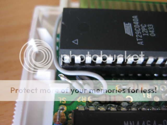
For my first try, I took a FF3J (TNROM) since there is only one chip to remove. So I removed the chip. I didn't cut the traces, just bended the pins. Rerouted the proper pins for a flash epprom (AT29C040A).
(updated diagram again) Here's the chip diagrams side by side:
- Took pin 1 (A18) and connected it to hole 2
- Took pin 2 (A16) and connected it to hole 24
- Took pin 30(A17) and connected it to hole 1
- Took Pin 31 (WE) and 24 (OE), connected them together then connected it to pin 16 (GND)
I tested all the pins and none of them touch each other.
To test the results, I decided to use the same rom as the original game to make sure the board works. I took a rom and stripped the ines header, flash it. For now I only have a grey screen.
The possible error I see are:
- The content of the flash eprom is wrong
- I made a mistake in the wiring
- Since I inserted by mistake the board backward (... It was 2h in the morning), I may have fried the board
- Connecting WE to OE then to GND was not a good idea
I will try to continue to debug it tonight. Any comments about possible mistakes I made are appreciated.
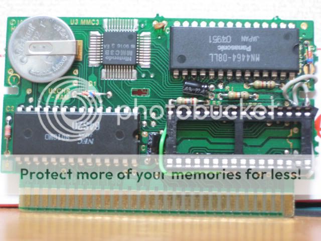
Here's a few pictures I took very fast this morning showing the board. Sorry, they are a little bit blurry.
Top of cartridge

Pin 17 to 32

Pin 16

Pin 1-2
Back of board

For my first try, I took a FF3J (TNROM) since there is only one chip to remove. So I removed the chip. I didn't cut the traces, just bended the pins. Rerouted the proper pins for a flash epprom (AT29C040A).
(updated diagram again) Here's the chip diagrams side by side:
Code:
AT29C040A - 512KBytes (32pin): PRG ROM - 512KBytes (32pin):
---_--- ---_---
A18 - |01 32| - VCC PRG A17 - |01 32| - +5V
A16 - |02 31| - /WE PRG A18 - |02 31| - +5V
A15 - |03 30| - A17 PRG A15 - |03 30| - +5V
A12 - |04 29| - A14 PRG A12 - |04 29| - PRG A14
A7 - |05 28| - A13 PRG A7 - |05 28| - PRG A13
A6 - |06 27| - A8 PRG A6 - |06 27| - PRG A8
A5 - |07 26| - A9 PRG A5 - |07 26| - PRG A9
A4 - |08 25| - A11 PRG A4 - |08 25| - PRG A11
A3 - |09 24| - /OE PRG A3 - |09 24| - PRG A16
A2 - |10 23| - A10 PRG A2 - |10 23| - PRG A10
A1 - |11 22| - /CE PRG A1 - |11 22| - PRG /CE
A0 - |12 21| - I/O7 PRG A0 - |12 21| - PRG D7
I/O0 - |13 20| - I/O6 PRG D0 - |13 20| - PRG D6
I/O1 - |14 19| - I/O5 PRG D1 - |14 19| - PRG D5
I/O2 - |15 18| - I/O4 PRG D2 - |15 18| - PRG D4
GND - |16 17| - I/O3 GND - |16 17| - PRG D3
-------
- Took pin 1 (A18) and connected it to hole 2
- Took pin 2 (A16) and connected it to hole 24
- Took pin 30(A17) and connected it to hole 1
- Took Pin 31 (WE) and 24 (OE), connected them together then connected it to pin 16 (GND)
I tested all the pins and none of them touch each other.
To test the results, I decided to use the same rom as the original game to make sure the board works. I took a rom and stripped the ines header, flash it. For now I only have a grey screen.
The possible error I see are:
- The content of the flash eprom is wrong
- I made a mistake in the wiring
- Since I inserted by mistake the board backward (... It was 2h in the morning), I may have fried the board
- Connecting WE to OE then to GND was not a good idea
I will try to continue to debug it tonight. Any comments about possible mistakes I made are appreciated.
Here's a few pictures I took very fast this morning showing the board. Sorry, they are a little bit blurry.
Top of cartridge
Pin 17 to 32
Pin 16
Pin 1-2
Back of board