Hey, everyone. Just a quick question about the video signal output by the NES.
It is my understanding that the NES outputs at 224p. In order to display this on SDTV the CRT display would skip over every other scanline (which is why emulators have a scanline option).
Fair enough. But in this video (
https://hooktube.com/watch?v=3BJU2drrtCM, the TV (presumably designed for NTSC SDTV) seems to be drawing every scanline with no 'dark' scanlines. This is also how I personally remember the picture looking as a child.
So whats happening here? How is the 224p picture being displayed on every line of a 525-line display and still taking up most of the screen?
First of all, the NES outputs 240p, not 224p - some scanlines might be obscured by your TV's bezel, but the PPU outputs all of them. Second, it's definitely progressive output, because the NTSC NES PPU outputs exactly 262 scanlines per frame (312 for PAL), not 262.5 as per the NTSC specifications (312.5 for PAL), and the lack of that final half scanline is what makes it progressive instead of interlaced.
The most likely reason you don't see inter-scanline gaps is probably because that video was recorded on a rather small screen, so the gaps would've been extrremely small; on a larger screen, they likely would've been more noticeable. The "100% scanlines" effect presented by most emulators is highly exaggerated, and real TVs (especially small ones) didn't actually look like that.
In order to see that it's actually progressive rather than interlaced, you'd need to see a recording of two consecutive frames to see that the scanlines from each frame are perfectly aligned with the scanlines from the frame immediately preceding/following it.
It seems you misunderstand how a CRT works. There is no "on every line" on a CRT. It is just a surface where the electron gun can "paint". It does this by scanning in lines from left to right, top to bottom. The "dark lines" you are referring to are the gaps between the lines that are drawn. Depending on the focus of the beam and the size of the display, these gaps are more or less visible.
Nioreh wrote:
It seems you misunderstand how a CRT works. There is no "on every line" on a CRT. It is just a surface where the electron gun can "paint". It does this by scanning in lines from left to right, top to bottom. The "dark lines" you are referring to are the gaps between the lines that are drawn. Depending on the focus of the beam and the size of the display, these gaps are more or less visible.
So does the screen display higher resolutions than 240p (e.g. 480i) by focusing the beam into a smaller 'dot'?
A CRT is an analog device: there is a beam of electrons that is rapidly scanned across a screen covered in phosphors.
The size of the dot is almost never tuned at operation time: every CRT is optimized for a given fixed resolution. 240p vs 480i is just a question of whether the electron beam is at the exact same vertical offset every vsync or offset by half.
Smaller CRTs don't (can't?) tune the dot small enough to meaningfully achieve visible interlacing. Most TVs include a specification of the number of vertical lines: this is a specification of how large the electron beam is relative to the size of the phosphor screen.
AzimuthFE wrote:
Nioreh wrote:
It seems you misunderstand how a CRT works. There is no "on every line" on a CRT. It is just a surface where the electron gun can "paint". It does this by scanning in lines from left to right, top to bottom. The "dark lines" you are referring to are the gaps between the lines that are drawn. Depending on the focus of the beam and the size of the display, these gaps are more or less visible.
So does the screen display higher resolutions than 240p (e.g. 480i) by focusing the beam into a smaller 'dot'?
The lines would just overlap in 480i mode. Actually, it's a good thing if interlacing lines overlap, because it makes interlacing artifacts less noticeable.
Some TVs will not show any black lines between scanlines at all, while others have big black gaps.
My 1981 trinitron has no gaps, but a newer JVC TV has huge gaps.
I've never, ever, seen any TV display anything remotely similar to what emulators pass off as "scanlines", be it 100%, 50% or even 25%. I could never understand why those options existed.
One of the big factors is that the size of the electron beam correlates with the brightness. (You can only get so high of an electron flux before you start pulling electrons off more)
So the standard "Just put a simple line in between" doesn't even look close to authentic. Not even on an old VGA CRT where the electron guns have the same effect going on, because the electron beam is tuned to be much much smaller there.
Modern openGL shader emulations of CRT bloom actually begin to approach feeling authentic.
I once borrowed 4 tv sets for showing off some of my graphics side by side, and it was also insightful to see how much the same image could look differently across different screens. One had a very distinct scanline spacing and it was the first time i've actually seen that on a tv.
...and it, as lidnariq points out, didn't look much like the "emulation" effect.
Thanks for all the replies, guys. I think I understand now.

So in interlacing mode the 'even' scanlines are offset by only half a scanline? If that's the case I had one last question: How does the TV know to use interlace mode? Is there some part of the video signal?
In a CRT, the horizontal and vertical deflection coils basically move at one of two constant¹ rates: Down/Right at normal speed, or Up/Left much faster.
The TV separates out two signals from the incoming video that mean "go to top" (vertical sync) and "to to left" (horizontal sync); the relative timing of these two events controls whether the scanlines are skew or aligned.
¹Actually not very constant, because driving electromagnets is hard, and CRTs aren't perfect spherical sections
tokumaru wrote:
I've never, ever, seen any TV display anything remotely similar to what emulators pass off as "scanlines", be it 100%, 50% or even 25%. I could never understand why those options existed.
Most scanline filters suck, but there are some really good ones out there, and I greatly prefer it to just plain pixel-by-pixel displays, which looks really fake, and nothing like how anyone ever experienced the games at the times.
The problem is of course that you can't just skip every other line of pixels and call it a scanline, since an actual CRT display works with phosphor light, and you'd always have the colors "spill over" into the adjacent scanlines, which is why the picture never gets noticably darker from being progressive instead of interlaced, and the brightest colors would spill over much more than the dark ones - so you'd need a much higher resolution than just 2x or even 4x the original to reproduce a convincing scanline on a modern display.
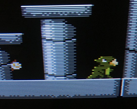
Here's a picture I took off my Sony PVM monitor - not the best photo, but I think it displays the scanlines well. It's one of the best CRTs ever produced, and a fan favourite among many "retro gamers". I think its scanlines makes the image look incredible. Most lower end consumer TVs (usually off-brand no-name stuff without RGB inputs, VHS combi-TVs, etc.) tended to have a much more blurry image, which also obscured the scanlines. Whether you like scanlines or not, that kind of messy image quality really isn't desirable.

tokumaru wrote:
I've never, ever, seen any TV display anything remotely similar to what emulators pass off as "scanlines", be it 100%, 50% or even 25%. I could never understand why those options existed.
One reason it doesn't look similar is because it's not 50/50 image and black line. Sumez's picture shows that it's a far thinner line. So to do this in an emulator you'd need to run at much higher resolutions that older computers couldn't handle. But it could handle the 50/50 scanline effect which does give the image a certain look to it that some people like and some people don't. But I think that's why it exists.
How the scanlines appear is a product of the beam focus and convergence, which is influenced by tube age / emission, proper alignment of convergence rings, yoke positioning, and quality of the tube in the first place.
Remember that the actual lines are scanned out, and there's no magic to "the scanlines"; they are just the gaps between the actually scanned lines. An emulator filter or shader isn't going to wholly capture "the look of scanlines" because every type of tube is different, even before condition is taken into account.
That said, you could make a filter that comes very close to looking like what one particular CRT
could look like, especially with the monitor resolutions that are available today.
And I think there are actually already some very good ones out there.
But at least we can all agree that just drawing a black line every second line isn't the way to go.

Sumez wrote:
That said, you could make a filter that comes very close to looking like what one particular CRT could look like, especially with the monitor resolutions that are available today.
So basically you're saying that 4k resolution finally have an usage other than pure commercial?
Even a 720p TV should be able to give a passable simulation of beam spreading at 3x zoom.
I think emulated scan lines look way too dark. If a CRT has dark spaces between lines, the lines are usually bright enough to compensate for it. On an LCD you can't have black and white stripes and still make it look white.
psycopathicteen wrote:
If a CRT has dark spaces between lines, the lines are usually bright enough to compensate for it. On an LCD you can't have black and white stripes and still make it look white.
Yes, this is a very important aspect of it. If the beam isn't interlacing it is concentrating twice as much light on half the space (i.e. no change in overall intensity vs. interlaced mode). There is no equivalent range of intensity on an LCD with emulated scanlines. Plus CRTs are brighter than LCDs just as a baseline factor, even before taking into account scanlines.
rainwarrior wrote:
psycopathicteen wrote:
If a CRT has dark spaces between lines, the lines are usually bright enough to compensate for it. On an LCD you can't have black and white stripes and still make it look white.
Yes, this is a very important aspect of it. If the beam isn't interlacing it is concentrating twice as much light on half the space (i.e. no change in overall intensity vs. interlaced mode). There is no equivalent range of intensity on an LCD with emulated scanlines. Plus CRTs are brighter than LCDs just as a baseline factor, even before taking into account scanlines.
The "solution" is to just have a cranked up LCD backlight, but that's kind of janky. No matter how you look at it, emulating scanlines sacrifices total luminosity.
To say CRTs are brighter than LCDs is a bit of an umbrella statement that's untrue in a lot of cases, but your average CRT TV / 15Khz monitor in good shape will be very bright. A PC CRT is often quite a bit dimmer.
For what it's worth, this is what a nearly NOS 32" tube looks like - and it's not a PVM, or other fancy broadcast video monitor. Just a big honking slot mask curved tube.
(Using a game I expect most people here to recogniz!)
mikejmoffitt wrote:
The "solution" is to just have a cranked up LCD backlight, but that's kind of janky. No matter how you look at it, emulating scanlines sacrifices total luminosity.
To say CRTs are brighter than LCDs is a bit of an umbrella statement that's untrue in a lot of cases, but your average CRT TV / 15Khz monitor in good shape will be very bright. A PC CRT is often quite a bit dimmer.
Yeah, I was overstating it a little but I did mean in general, and I was a little bit conflating with contrast, i.e. turning up the backlight will also noticably raise the black level. ...but some LCDs are better than others, of course, and the technology has improved over the years.
Take a look at this zoom up of a Pac-Man CRT.

It appears to have horizontal scanlines. But, if you look closely, that effect is actually a consequence of the delta-gun shadow mask and phosphor dot layout. In fact, the monitor is rotated 90 degrees; the electron gun is actually sweeping vertically. I bring this up to point out that "scanlines" are not just the result of highly focused beams.
Scanlines are literally the result of focused beams. Those horizontal lines are as you mentioned just a result of the phosphor layout, and aren't scanlines.
Sure, but his point is that the phosphor layout is also a visible artifact, and the individual phosphor elements are often large enough to be important to the correct emulation of scanlines.
I mean, not on a Trinitron tube (or
my TV). But for anything with the more conventional triangular electron gun arrangement...
I never actually considered that detail, so it's cool to have pointed out.
What a horrible monitor in that image, though

I don't think I've ever seen Pac-Man looking that blurry.
Here are a few more Pac-Man pics:
https://i.imgur.com/mC1VCf8.jpghttps://i.imgur.com/qBhnD3z.jpghttps://i.imgur.com/75VOAMw.jpghttps://i.imgur.com/nHumYlc.jpghttps://i.imgur.com/ST5974d.jpghttps://i.imgur.com/Q9UBSCU.jpghttps://i.imgur.com/mDcgJw8.jpgApparently, it's an in-line color mask, not delta format. The pic posted earlier in this thread was apparently too blurry. Though, I have seen machines where the pseudo-horizontal-scanlines were highly pronounced with clear gaps between the rows.
Also, I always wondered why a brick pattern is used as opposed to what you see in Trinitron monitors. Was it due to technological limitations or was it an attempt to reduce visible scanlines?