I don't know where to put this question, so I try it here because I assume you know about the various quirks of NES games.
I bought an old CRT TV to play NES games (TV and NES are both NTSC). But for some reason, whenever a Goomba is on the standard blue background, his left side seems to have a white diagonal line. It somehow looks like this:

Of course, I know this has nothing to do with the NES itself and how the sprites are represented in the game. It must have to do with how the TV composes the colors.
It only happens when the Goomba is on the blue background. When he's in a dungeon or in front of a bush or hill, everything is fine. And it's only on its left side.
Mario himself has a similar color curiosity as well.
So, does anybody know how this comes to be? Did anybody of you see this phenomenon on his TV as well and can anybody give me a technical explanation for it and maybe tell me how to correct it? I already tried to adjust color, brightness, contrast, sharpness, tint etc., but until now, it didn't help much. (Only that I was able to turn the white color purple by playing with the tint.)
Sharpness should be turned down near the bottom of the range.
There are two possibilities. One is "bleed", or interference between the brightness and color components. Composite video puts both components into different frequency bands of one signal, and pre-PlayStation consoles weren't very good at keeping them separate. It's especially noticeable on vertical or diagonal lines between colors of the same brightness but different hue. Later games incorporated dark outlines into sprite designs to make this less noticeable. Another is convergence failure, where misaligned electron guns or inaccurate delays in the NTSC decoder cause, say, red to be drawn a fraction of a pixel to the left and blue a hair to the right.
Thanks for the answer.
I already put sharpness at zero.
Is there any way I can correct this? And is this a common problem with American TVs or is this phenomenon rare and I should just go and find another one?
Can you photograph the TV with a camera so I can see the exact artifacts?
Does it look something like this?

(heh, thumbnail is a bigger file than the actual image)
tepples wrote:
Can you photograph the TV with a camera so I can see the exact artifacts?
Sorry, I don't have a camera. I would have to get one from somewhere. But I think that's not necessary anymore because:
Dwedit wrote:
Does it look something like this?
Yes, that's pretty much what I was talking about. I tried it out with Nestopia myself and you can even see the effect that the white border disappears when the Goomba walks in front of the bush or a hill.
So, is this an effect that is common for NTSC TVs and it's just supposed to be like that? (I'm from Germany and we have PAL. Only for the NTSC NES, I bought the NTSC TV. But on a PAL NES on a PAL TV, I don't see the effect.) Or do other TVs render it better?
Or do you even know what combination of the image values will remove it? In the moment, all my values are set to 50 %, except for contrast, which is at 100 %. These are the default settings. Additionally, I manually set sharpness to 0 %.
PAL video has more space between the brightness and color frequencies than NTSC video does, which makes the white lines harder to see on a PAL NES.
I don't know if this is related, but on my modern LCD TV, if I let is set-up as default, NES games will look horrible with very bright vertical lines at every color changes.
If I reduce the sharpness to 0% the signal is filtered and it looks close to what it should on a good old CRT TV.
This is for both NTSC and PAL (modern TVs accepts both thankfully).
I'm not sure what you're complaining about. That screenshot looks exactly like what I've been playing for 25 years

I think emulators spoil us sometimes.
Although I can see how if you've never dealt with NTSC pictures it would be off-putting. I just grew up with shite video. Good ol' American ingenuity at it's best. Whether we do it first or do it last, we always half-ass it
So, can you all confirm that this is basically what NTSC looks like and that it looks this way on basically every CRT NTSC TV?
The picture DW edit posted with Blargg's filter is basically 100% accurate to what I've always seen on every CRT I've played on. And I'vep layed probabkly 10 different NES's on at minimum 3 TV's each, so yeah.
Attachment:
File comment: Macro photo of an NTSC TV displaying a Goomba in World 1-1 of Super Mario Bros. Notice the white ringing on the right edge.
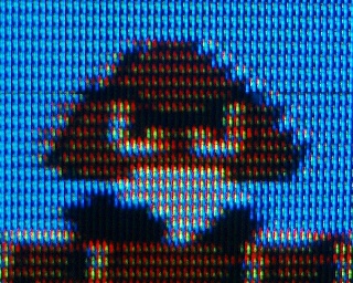 NTSC_goomba.jpg [ 60.48 KiB | Viewed 2816 times ]
To quote
Wayne's World: "Extreme close-up!"
To quote King Dedede's final smash in
Super Smash Bros. Brawl: "Goomba, Goomba, crap crap crap!"
OK, thanks a lot for your answers.
Best Wayne's World reference on the board I'd say
qbradq wrote:
Although I can see how if you've never dealt with NTSC pictures it would be off-putting. I just grew up with shite video. Good ol' American ingenuity at it's best. Whether we do it first or do it last, we always half-ass it
Whoever designed the original B&W television standard obviously didn't think about color expandability. Before NTSC, there was an older RGB color television starndard, but it was short lived, thanks to the FCC complaining about backwards compatibility.
NTSC is only marginally backwards compatible anyway... nasty dot hatch patterns appear on old monochrome sets.
So all the black and white TV sets that came out after Color TVs were invented will filter out the hatch patterns?
psychopathicteen: I would be surprised if it were only the FCC that complained about backwards compatibility.
mikejmoffitt: Given the constraint of "not using more bandwidth" and "backwards compatible", everything will have that flaw. (You get equally visible chroma crosstalk with PAL or SECAM inputs)
dwedit: I assume that was rhetorical, given the use of "all"? (No, they don't)
I think it's funny that, back in the 1960's, the philosophy behind the economical growth was different, and they made all these efforts for backwards compatibility.
If this were to happen with today's marketing mentalities, they would have made the new standard non backwards compatible on purpose, then stop to transmit the emissions in the old monochrome standard, to force everyone to buy new TVs.
Yes, because electronics today are pretty cheap. Back then, a TV was like a car or something, not something you could easily replace.
I actually didn't mean that rhetorically, but did B&W TVs made after Color became standard start to filter out the color parts of the signal to make the black & white portion look better?
Dwedit wrote:
I actually didn't mean that rhetorically, but did B&W TVs made after Color became standard start to filter out the color parts of the signal to make the black & white portion look better?
I'm about 90% certain they didn't. I've never seen a monochrome RS170 set with a CRT bigger than 12", and all of the larger ones were real monitors that used the higher bandwidth available (so wouldn't have a chroma killer). All of the rest I've seen were small portable ones, and once they excluded color display for cost or weight, and lacked RCA input, and the screen was so tiny (3-6") that 1- the electron beam size was comparable to the chroma dot size, so dot crawl wasn't terribly visible, 2- in case of cost savings, the only cheap chroma killer would be rather blurry and 3- NTSC OTA demodulation already is noisy and bandlimited enough that most chroma dots are drowned out.
I wonder what kind of low pass filters did televisions use. These are the kinds of LPF I know.
sinc: perfect roll-off, but far too expensive to implement
boxcar: Weak roll-off
gaussian: Weak roll-off
RC: Easiest to implement in analog hardware, but has the weakest roll-off
psycopathicteen wrote:
sinc: perfect roll-off, but far too expensive to implement
too expensive to implement
in analog; also the analog FIR filters are really funny and still discretized in time.
Quote:
boxcar: Weak roll-off
Other than ease of implementation, I can't figure out when would ever use one. Also awkward to implement in analog.
Quote:
gaussian: Weak roll-off
Yeah, gaussian's optimized for minimal spatial/temporal smear/blur. Also is noncausal, so impossible to implement in analog.
Quote:
RC: Easiest to implement in analog hardware, but has the weakest roll-off
But there are so many kinds! Try asking wikipedia about any of the following: Chebychev, Butterworth, Elliptical, Constant k. Although wikipedia's description of the first 3 are all discrete-time variants, they all exist for both discrete and continuous time.
I have here a 1980s Zenith green and black monitor designed for computer use, made long after color CRTs emerged, and it certainly does not filter out the NTSC color burst.
Here is a picture of it running from a Model 1 japanese Mega Drive. The color burst shows itself in the form of vertical lines, not a hatch pattern as a Famicom might, as the MD does not vary the color burst over time. This preserves vertical lines better, but results in a more predictable field of artifacts.

An unchanging color carrier phase from one line to the next results in some colored vertical lines looking wider than others. When a colored object moves horizontally, it's really ugly. This is because the edge falls on different parts of the color carrier wave, and thus affect width differently based on position.
blargg wrote:
An unchanging color carrier phase from one line to the next results in some colored vertical lines looking wider than others. When a colored object moves horizontally, it's really ugly. This is because the edge falls on different parts of the color carrier wave, and thus affect width differently based on position.
Conclusion: NTSC is terrible
And conclusion #2 : Sega is terrible too

Sega VDPs aren't the only TMS9918-family VDPs that have this problem. Because the scanline is 342 pixels long, an even multiple of the color subcarrier, vertical lines at a given position will hit the same phase every time. NES and Super NES have a similar problem: check out the diagonal stripes in the checkerboard dithering on the title screen of Dr. Mario for NES.
There is in fact a way to correct this. It involves making the scanline 341.25 dots long (exactly the same as the NTSC standard), and then making the post-render line 342 dots long instead of 341.25 to correct the phase for the next frame. But like the Johnson counter that divides by 16 instead of the expected 15 in the PAL NES CPU, it was Nintendo being stingy with the die size.
lidnariq wrote:
But there are so many kinds! Try asking wikipedia about any of the following: Chebychev, Butterworth, Elliptical, Constant k. Although wikipedia's description of the first 3 are all discrete-time variants, they all exist for both discrete and continuous time.
The pages on Wikipedia are complicated and confusing, and I beleive I even found a contradiction between the "butterworth" page and the "digital filter" page.
The "butterworth" page states the transfer function H(s) of a 3rd-order butterworth filter is this:
H(s) = 1 / (1 + 2s + 2s^2 + s^3)
plugging the above into the mathematical formula on the "digital filter" page:
H(z) = Y(z) / X(z) = 1 / (z^3 + 2z^2 + 2z + 1)
multiply numerator and denominator by z^-3
H(z) = Y(z) / X(z) = z^-3 / (1 + 2z^-1 + 2z^-2 + z^-3)
(1 + 2z^-1 + 2z^-2 + z^-3) * Y(z) = (z^-3) * X(z)
inverse Z transform
y(n) + 2y(n-1) + 2y(n-2) + y(n-3) = x(n-3)
y(n) = x(n-3) - 2y(n-1) - 2y(n-2) - y(n-3)
This is what I got following the math on Wikipedia, and this does not look like a lowpass filter to me. Why would you subtract the recursive samples, and delay the only nonrecursive sample?
Butterworth just means the filter is optimized for a constant gain and no phase shift in the bandwidth, with a quality factor of 0.7
It can be any type of filter, analog or digial, lowpass, highpass or bandpass, but should be at least of 2nd order.
(else, for 1st order filters, there is only a single parameter - the cutoff frequency - and then no way to optimize it for different applications)
What makes Butterworth/Ecliptic/Chevychev filters complicated for me is that I can only find information on the frequency responce, and I don't know how to translate it into a convolution function.
psycopathicteen wrote:
The "butterworth" page states the transfer function H(s) of a 3rd-order butterworth filter is this:
H(s) = 1 / (1 + 2s + 2s^2 + s^3)
plugging the above into the mathematical formula on the "digital filter" page:
H(z) = Y(z) / X(z) = 1 / (z^3 + 2z^2 + 2z + 1)
I can't find where on Wikipedia:Digital Filter you were told that you can just substitute z for s. (You can't).
The process of converting continuous time filters to discrete time filters is full of gross math. (ISTR sometimes using tan(x)). So as a result, digital filters are usually designed to the same constraints as the analog ones and not converted.
IIR filters aren't done via convolution so you probably won't be looking at the impulse response. Looking at the transfer function, as I've plotted here, is usually more useful.

This is why NESDEV rocks so hard! Ya'lls some hard-core nerds
I found on the wiki page for "Z Transform" it says:
s = (2 / T) * (z - 1) / (z + 1)
I'm guessing that these are the same "s" and "z" we talked about earlier. So I plugged this into the equation above (with a T value of 1), and I got:
y(n) = ( x(n) + 3x(n-1) + 3x(n-2) + x(n-3) + 25y(n-1) - 15y(n-2) + 3y(n-3) ) / 21
Are my assumptions correct?
I think you have a minor error at the end? I asked a CAS and got
H(z) = (z+1)³/(21z³-25z²+15z-3)
aka three poles at +⅓ and (3±√-12)/7 and three zeroes at -1
which should work out to
H(z¯¹) = (z¯¹+1)³/(21-25z¯¹+15z¯²-3z¯³)
y[n] = x[n]+3x[n-1]+3x[n-2]+x[n-3] + 21y[n]-25y[n-1]+15y[n-2]-3y[n-3]
Be careful; by choosing a T of 1, you are specifying a sample rate of 1 Hz, which may not be what you want. Of course, the equation you were given for a continuous-time Butterworth filter has a corner frequency of 1rad/sec, so maybe it is what what you want.
Here's the transfer function I got:
Attachment:
File comment: H(z) = (z+1)³/(21z³-25z²+15z-3)
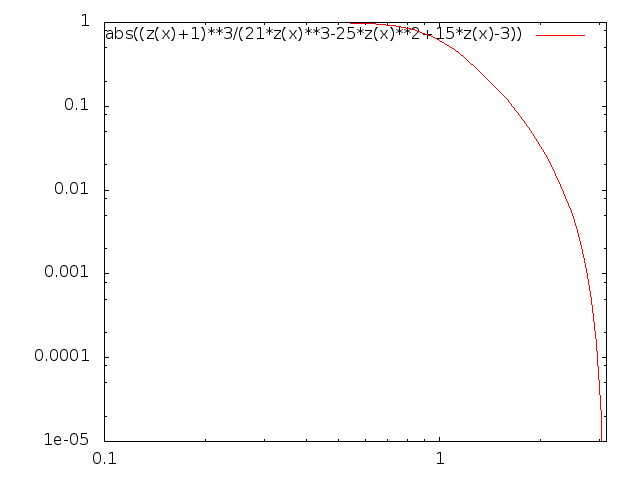 discretized-butterworth.png [ 4.49 KiB | Viewed 1211 times ]
You'll notice that the lowpass characteristic is nowhere as nicely smooth as the continuous time version I plotted before. That's because the bilinear transform
sucks.

You can ask wolfram alpha to
plot the impulse
response for you. I had to split it in two that can be added together because all at once exceeds what they're willing to do for you for free.