Your PCB foundry will tell you their requirements.
For example, ITEAD lists what they can do ("PCB capabilities", also, if you're using Eagle, section "Download" with CAM and DRC files)
For a DIP design, you mostly don't care about soldermask (although it's still nice), and for the design you have there, you basically aren't using any silkscreen either.
I don't know what the famicom PCB's thickness is, but the NES is the (less common) 1.3mm; using too thick a board will damage the card-edge slot. (Using too thin a board won't reliably make contact)
It seems this is nice :
Type : 2 Layer
Material : FR4
Thickness : 1.2mm
Soldermask : yes
Silkcreen : yes
Surface Finish : ENIG
Cut : CNC-Router
But it costs a lot, so how is this one :
Type : 2 Layer
Material : FR4
Thickness : 1mm
Soldermask : No
Silkcreen : No
Surface Finish : HASL
Cut : CNC-Router
Thanks in advance
Type : 2 Layer
Material : FR4
Thickness : 1.2mm
Soldermask : yes
Silkcreen : yes
Surface Finish : ENIG
Cut : CNC-Router
But it costs a lot, so how is this one :
Type : 2 Layer
Material : FR4
Thickness : 1mm
Soldermask : No
Silkcreen : No
Surface Finish : HASL
Cut : CNC-Router
Thanks in advance
You should measure the thickness of games you already have and match. And, unfortunately, that's the one thing you mustn't change; too thin won't reliably make contact and too thick will damage the famicom's connector.
Otherwise, I agree that you don't need soldermask (very minor implications about durability) or silkscreen (just pretty ... maybe there's some protective effects for the reversed "silkscreen everywhere" I've seen occasionally).
ENIG (gold plating on top of nickel on top of the copper in the PCB) is more durable than HASL (a layer of solder over all the exposed copper), but other than whatever this implies about the edge connector, you again don't really care for a DIP design.
Thanks for the answer
It seems ENIG doesn't add much thickness to the PCB :

But HASL adds at least 100 Micron (0.1mm) to the PCB :

So using 1mm PCB with HASL (on double side) will be at least 1.2mm which seems good, no?
It seems ENIG doesn't add much thickness to the PCB :

But HASL adds at least 100 Micron (0.1mm) to the PCB :

So using 1mm PCB with HASL (on double side) will be at least 1.2mm which seems good, no?
Other sources I've seen imply a much more variable thickness of HASL coatings. (e.g. http://www.ncabgroup.com/surface-finishes-2/ says 1 to 40µm; https://dcchapters.ipc.org/assets/pnw/p ... nishes.pdf says anywhere from 25 to 2000µm ). You should talk to the PCB manufacturer to ask what they'll be able to deliver.
I have just ordered 2 PCB to a local manufacturer, It costs 6$ (3$ per PCB), I hope the quality will be fine.
Quote:
The only problem is they didn't cut the board edge!
That sucks!
Other than that it looks decent. What mapper are you using for the MMC3? I'm assuming the AX5202?
Wow, nice boards for that much money each and such a small amount of boards! One trick you can also use is to have them drill a line of holes where you plan on cutting the board, later. This makes removing the edges much easier. I've seen some mass-produced boards that seem to do this. I've also seen wires that ended on the edge (probably for quality control?).
Looking up the words "perforated" or "perfboard" on Google gives me these examples:
https://www.perforatedpaper.com/MoreInfo.aspx
http://www.allelectronics.com/make-a-st ... ard/1.html
On Wikipedia:
http://en.wikipedia.org/wiki/Perfboard
Looking up the words "perforated" or "perfboard" on Google gives me these examples:
https://www.perforatedpaper.com/MoreInfo.aspx
http://www.allelectronics.com/make-a-st ... ard/1.html
On Wikipedia:
http://en.wikipedia.org/wiki/Perfboard
It can be used for these purpose :
TLROM :
MMC3 --> AX5202P
PRG-ROM --> M27C322
CHR-ROM --> M27C322
TSROM :
MMC3 --> AX5202P
PRG-ROM --> M27C322
PRG-RAM --> KM62256
CHR-ROM --> M27C322
TKROM :
MMC3 --> AX5202P
PRG-ROM --> M27C322
PRG-RAM --> FM1808
CHR-ROM --> M27C322
TGROM :
MMC3 --> AX5202P
PRG-ROM --> M27C322
CHR-RAM --> KM62256
TNROM :
MMC3 --> AX5202P
PRG-ROM --> M27C322
PRG-RAM --> FM1808
CHR-RAM --> KM62256
8 IN 1 Mode :
74HC161
2.2K Resistor
104 Capacitor
1N4148 Diode
FARID wrote:
It can be used for these purpose :
TLROM :
MMC3 --> AX5202P
PRG-ROM --> M27C322
CHR-ROM --> M27C322
TSROM :
MMC3 --> AX5202P
PRG-ROM --> M27C322
PRG-RAM --> KM62256
CHR-ROM --> M27C322
TKROM :
MMC3 --> AX5202P
PRG-ROM --> M27C322
PRG-RAM --> FM1808
CHR-ROM --> M27C322
TGROM :
MMC3 --> AX5202P
PRG-ROM --> M27C322
CHR-RAM --> KM62256
TNROM :
MMC3 --> AX5202P
PRG-ROM --> M27C322
PRG-RAM --> FM1808
CHR-RAM --> KM62256
8 IN 1 Mode :
74HC161
2.2K Resistor
104 Capacitor
1N4148 Diode
TLROM :
MMC3 --> AX5202P
PRG-ROM --> M27C322
CHR-ROM --> M27C322
TSROM :
MMC3 --> AX5202P
PRG-ROM --> M27C322
PRG-RAM --> KM62256
CHR-ROM --> M27C322
TKROM :
MMC3 --> AX5202P
PRG-ROM --> M27C322
PRG-RAM --> FM1808
CHR-ROM --> M27C322
TGROM :
MMC3 --> AX5202P
PRG-ROM --> M27C322
CHR-RAM --> KM62256
TNROM :
MMC3 --> AX5202P
PRG-ROM --> M27C322
PRG-RAM --> FM1808
CHR-RAM --> KM62256
8 IN 1 Mode :
74HC161
2.2K Resistor
104 Capacitor
1N4148 Diode
Do I smell megaman 6in1?
nintendo2600 wrote:
Do I smell megaman 6in1? 
Right it can be used for that too, soon I will make one.
Hmm, just realized - although it would likely end up costing you just as much in the end, you could electroplate those contacts to reach 1.2mm thickness on the 1mm boards. But since you have working boards, I guess it's a non-issue.
I add a 74HC4053 to the PCB :

So the new design is more flexible now :

So it is possible to make a Killer 6 IN 1 multicartridge with it :
Game 1 --> TSROM (256 + 256) --> Felix the Cat (U) [!].nes [&Menu]
Game 2 --> TGROM (256 + 8 ) --> Megaman II (U) [!].nes
Game 3 --> TSROM (256 + 256) --> Super Mario Bros. 3 (U) (PRG1) [!].nes
Game 4 --> TGROM (256 + 8) --> Contra (U) [!].nes
Game 5 --> TNROM (512 + 8) --> Final Fantasy III (J) [!].nes
Game 6 --> TKROM (512 + 512) --> Kirby's Adventure (U) (PRG1) [!].nes
@ alphamule
Thanks for the great info in the PM
It seems nothing can really replace 4053

So the new design is more flexible now :

So it is possible to make a Killer 6 IN 1 multicartridge with it :
Game 1 --> TSROM (256 + 256) --> Felix the Cat (U) [!].nes [&Menu]
Game 2 --> TGROM (256 + 8 ) --> Megaman II (U) [!].nes
Game 3 --> TSROM (256 + 256) --> Super Mario Bros. 3 (U) (PRG1) [!].nes
Game 4 --> TGROM (256 + 8) --> Contra (U) [!].nes
Game 5 --> TNROM (512 + 8) --> Final Fantasy III (J) [!].nes
Game 6 --> TKROM (512 + 512) --> Kirby's Adventure (U) (PRG1) [!].nes
@ alphamule
Thanks for the great info in the PM
It seems nothing can really replace 4053
Quote:
<Farid_> but it doesn't have any DIP package
<alphamule> Ah
<alphamule> Ah
Oh well, I tried. Yeah, it's the closet I could find. All the switches with more than 3 channels all seem to be bussed (as in, same select pins)! Finding one with only half the channels sharing a select pin was a royal PITA since a lot of the parts searches won't tell you that and there's 1000's of Mux/switch parts.
alphamule wrote:
Oh well, I tried. Yeah, it's the closet I could find. All the switches with more than 3 channels all seem to be bussed (as in, same select pins)! Finding one with only half the channels sharing a select pin was a royal PITA since a lot of the parts searches won't tell you that and there's 1000's of Mux/switch parts.
Anyway thank you very much, I really appreciate it.
Transcribing the function table from the image for posterity's sake:
D7 -> PRGA20 and CHRA20 and PRGsize[0:256 1:512]
D6 -> PRGA19 and CHRA19
D5 -> PRGA18 (but mux) and CHR A18 and CHR style
D0 -> clock latch
How is it ever possible to get CHR A18 high with CHR ROM ?
Implementation:
One multiplexer uses D7 to select whether PRGA18 comes from D5 or MMC3
Two multiplexers combined to make a demultiplexer uses D5 to select whether CHRRAM or CHRROM is enabled.
Anyway, what would you do with more than three multiplexers?
Code:
PRG CHR A18 A19 A20 TYPE
1 256 256 0 0 0 TLROM / TSROM
2 256 8 1 0 0 TGROM
3 256 256 0 1 0 TLROM / TSROM
4 256 8 1 1 0 TGROM
5a 512 256 0 0 1 \
5b 512 8 1 0 1 / T[ GKLNS ] ROM
6a 512 256 0 1 1 \
6b 512 8 1 1 1 / T[ GKLNS ] ROM
Registers:1 256 256 0 0 0 TLROM / TSROM
2 256 8 1 0 0 TGROM
3 256 256 0 1 0 TLROM / TSROM
4 256 8 1 1 0 TGROM
5a 512 256 0 0 1 \
5b 512 8 1 0 1 / T[ GKLNS ] ROM
6a 512 256 0 1 1 \
6b 512 8 1 1 1 / T[ GKLNS ] ROM
D7 -> PRGA20 and CHRA20 and PRGsize[0:256 1:512]
D6 -> PRGA19 and CHRA19
D5 -> PRGA18 (but mux) and CHR A18 and CHR style
D0 -> clock latch
How is it ever possible to get CHR A18 high with CHR ROM ?
Implementation:
One multiplexer uses D7 to select whether PRGA18 comes from D5 or MMC3
Two multiplexers combined to make a demultiplexer uses D5 to select whether CHRRAM or CHRROM is enabled.
Anyway, what would you do with more than three multiplexers?
Thanks for the new table.
It is more easy to understand the function.
When CHR A18 is high, CHR-ROM is disabled and CHR-RAM is enabled
I just wanted to see if there is any better TTL instead of 4053, but it seems the best TTL is 4053 itself
But with another mux maybe it is possible to protect WRAM :
D6 -> PRGA19 and CHRA19 and WRAM /WE [0:Dis 1:En]
Some TLROM games like Ninja Gaiden III may mess up with the wram so it is not possible to use a TKROM or TNROM for any of the Game1 ~ Game4
It is more easy to understand the function.
Quote:
How is it ever possible to get CHR A18 high with CHR ROM ?
When CHR A18 is high, CHR-ROM is disabled and CHR-RAM is enabled
Quote:
Anyway, what would you do with more than three multiplexers?
I just wanted to see if there is any better TTL instead of 4053, but it seems the best TTL is 4053 itself
But with another mux maybe it is possible to protect WRAM :
D6 -> PRGA19 and CHRA19 and WRAM /WE [0:Dis 1:En]
Some TLROM games like Ninja Gaiden III may mess up with the wram so it is not possible to use a TKROM or TNROM for any of the Game1 ~ Game4
FARID wrote:
When CHR A18 is high, CHR-ROM is disabled and CHR-RAM is enabled
So then there's no way to ever select CHR-ROM banks when that bit is high? Then why connect it to CHR-ROM at all? It seems to require a twice-as-large CHR ROM for no purpose?lidnariq wrote:
So then there's no way to ever select CHR-ROM banks when that bit is high? Then why connect it to CHR-ROM at all? It seems to require a twice-as-large CHR ROM for no purpose?
Yes, you are right, CHR-ROM will be 1MB at most, so the best EPROM is 27C080
But as you may know 27C080 is more expensive than 27C322 so I decided to use the cheaper EPROM in spite of wasting half of it
On the other hand A18 of 27C322 can be tied to GND and then control the other high address lines with D7 and D6 but this will make the registers even more complex :
CHR A20 --> GND
CHR A19 & PRG A20 --> D7
CHR A18 & PRG A19 --> D6
PRG A18 --> D5
So I decided to keep the registers as simple as possible, because I am wasting the half of the EPROM anyway.
I guess these old 27C series UVEPROMs are the only DIP options at all... and perhaps the price difference is because more people had use for 1 MiWx8 than for 2 MiWx16 'PROMs.
If you ever do try surface mount, there are a few 5V 1MB+ options ( M29F800, MX29F800, M29F160 )
If you ever do try surface mount, there are a few 5V 1MB+ options ( M29F800, MX29F800, M29F160 )
Are you really this desperate about the price?? A 27C322 may be cheaper, OK but when you really compare the prices, 27C322 is about 2$ a piece while 27C080 is about 3-4$ at most but 27C080 is MUCH shorter (32pins instead of 42) so you save much more space on board and you save much more time for your work and it is much less complicated at the same time...
lidnariq wrote:
I guess these old 27C series UVEPROMs are the only DIP options at all... and perhaps the price difference is because more people had use for 1 MiWx8 than for 2 MiWx16 'PROMs.
If you ever do try surface mount, there are a few 5V 1MB+ options ( M29F800, MX29F800, M29F160 )
If you ever do try surface mount, there are a few 5V 1MB+ options ( M29F800, MX29F800, M29F160 )
If I want to use SMD, I will use DA28F640J5 (8MB) for sure, then I can even expand the circuit to use its all capacity!
MaarioS wrote:
Are you really this desperate about the price?? A 27C322 may be cheaper, OK but when you really compare the prices, 27C322 is about 2$ a piece while 27C080 is about 3-4$ at most but 27C080 is MUCH shorter (32pins instead of 42) so you save much more space on board and you save much more time for your work and it is much less complicated at the same time...
Yes the price is very important, on the other hand 27C322 is 4MB while 27C080 is only 1MB, with a better circuit I can use its all capacity!
Also by using a simple adapter, programming 27C322 is as simple as programming a 27C080 :

By the way, using 27C322 as CHR-ROM is better because by using only 2 wires instead of 4053 it is possible to change the whole cartidge to TSROM 8 IN 1
Even by installing a MMC1 through an adapter instead of AX5202P it is possible to make a SLROM 8 IN 1
Using a larger EPROM can make the whole cartridge flexible and general purpose
Another advantage to such a large memory is (especially if you socket it, but also if you have many of them) you can reuse it for say, a SNES or MegaDrive/Genesis or even a large custom game using a compatible mapper.
So here is the Menu of this multicart, the source code is also included  :
:

Here is the latest source code :
Menu for MMC3 games
Menu for MMC1 games

Here is the latest source code :
Menu for MMC3 games
Menu for MMC1 games
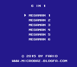
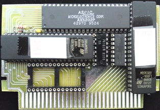
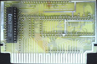
I made a Megaman 6 IN 1 :
Menu :
Front :
Back :
Full Schematic :
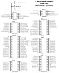
Mapper Schematic :
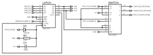
Chips :
M27C322 --> PRG-ROM
M27C322 --> CHR-ROM
KM6264 --> CHR-RAM
AX5202P --> MMC3
74HC161 --> Latch
74HC4053 --> Switch
Multicart registers :
D7 --> PRG A20, CHR A20, PRG Size [0:256 1:512]
D6 --> PRG A19, CHR A19
D5 --> PRG A18, CHR A18, CHR Control [0:ROM 1:RAM]
D0 --> Multicart register [0:Enable 1:Disable]
PRG & CHR Structure :
ROM1 --> Megaman 5 --> 256 + 256 --> PRG + CHR --> 000X XXX1 --> 0000 0001 --> 01 --> Menu
ROM2 --> Megaman 1 --> 256 + 8 ----> PRG + SRAM -> 001X XXX1 --> 0010 0001 --> 21
ROM3 --> Megaman 3 --> 256 + 256 --> PRG + CHR --> 010X XXX1 --> 0100 0001 --> 41
ROM4 --> Megaman 2 --> 256 + 8 ----> PRG + SRAM -> 011X XXX1 --> 0110 0001 --> 61
ROM5 --> Megaman 4 --> 512 + 8 ----> PRG + SRAM -> 101X XXX1 --> 1010 0001 --> A1
ROM6 --> Megaman 6 --> 512 + 8 ----> PRG + SRAM -> 111X XXX1 --> 1110 0001 --> E1
Notes :
Free blocks of CHR-ROM must be filled up.
The pinout of PRG-ROM and CHR-ROM are not standard.
All games must be Mapper 4 / MMC3. To convert Megaman 1 and 2 to Mapper 4 you must use infidelity's patch
Please someone emulate this multicart, thanks.
Menu :

Front :
Back :
Full Schematic :
Mapper Schematic :
Chips :
M27C322 --> PRG-ROM
M27C322 --> CHR-ROM
KM6264 --> CHR-RAM
AX5202P --> MMC3
74HC161 --> Latch
74HC4053 --> Switch
Multicart registers :
D7 --> PRG A20, CHR A20, PRG Size [0:256 1:512]
D6 --> PRG A19, CHR A19
D5 --> PRG A18, CHR A18, CHR Control [0:ROM 1:RAM]
D0 --> Multicart register [0:Enable 1:Disable]
PRG & CHR Structure :
ROM1 --> Megaman 5 --> 256 + 256 --> PRG + CHR --> 000X XXX1 --> 0000 0001 --> 01 --> Menu
ROM2 --> Megaman 1 --> 256 + 8 ----> PRG + SRAM -> 001X XXX1 --> 0010 0001 --> 21
ROM3 --> Megaman 3 --> 256 + 256 --> PRG + CHR --> 010X XXX1 --> 0100 0001 --> 41
ROM4 --> Megaman 2 --> 256 + 8 ----> PRG + SRAM -> 011X XXX1 --> 0110 0001 --> 61
ROM5 --> Megaman 4 --> 512 + 8 ----> PRG + SRAM -> 101X XXX1 --> 1010 0001 --> A1
ROM6 --> Megaman 6 --> 512 + 8 ----> PRG + SRAM -> 111X XXX1 --> 1110 0001 --> E1
Notes :
Free blocks of CHR-ROM must be filled up.
The pinout of PRG-ROM and CHR-ROM are not standard.
All games must be Mapper 4 / MMC3. To convert Megaman 1 and 2 to Mapper 4 you must use infidelity's patch
Please someone emulate this multicart, thanks.


