My first reproduction (and first ever electronics project) of taking a Golf cart and turning it into a Burger Time was successful. I started with something easy and am trying to work my way up in complication. Now, I am in the process of creating a reproduction of Mother 1 on a PCB donor from Deja Vu. (I have a copy of Shadowgate that I will test out using sockets in the next project)
I have the eproms burned with the CHR and PRG, and I have everything wired and soldered into place according to the EPROM conversion information for TKROMs.
In the photo album on the link, it is clearly messy. However, everything is by the directions of the EPROM conversion txt file. Believe me, I double checked... triple checked...
http://imgur.com/a/lXMmAWhen I put the cartridge in to test it, it was a blank screen. Nothing. Now, I'm new to soldering pins to holes using wires. So, I'm wondering if this is an issue caused by my low level soldering skills. I have a multimeter (a tool I have never used before) and I know I need to check for continuity. How is this done? Where would I place my multimeter's probes on the chip/PCB/pin/hole/?? to determine if I did a crappy job soldering?
Also, any soldering technique advice is welcome.Shoot, if you have a picture of a reproduction cart using a TKROM PCB, that would also be extremely helpful.
If you want to test for continuity, you should test the very end of each line. Most often in this situation, one end is a gold-finger on the edge of the PCB, and the other end is the leg of a chip or other component you soldered in.
There's an old series of soldering videos by PACE that I think are pretty great at explaining how to solder. Start here:
https://www.youtube.com/watch?v=vIT4ra6Mo0s
When you check for continuity all your are doing is making sure there is a constant connection. Your multi-meter has a spot on it that kind of looks like a plus sign w/a triangle on left side. To make sure you have correct setting simply take your two leads red and black and touch them together, it should beep.
If you take a small piece of wire and touch the bare wire of one end to the red lead and the bare wire of the other end to the black lead it will beep, that means you have continuity. Like on the circuit boards one pin has a small trace leading to another pin. The Multi-meter should beep when touching those ends w/the leads (one on each end) if there are no breaks in the trace. If you hear the beep you have continuity, if no beep something is wrong.
Sorry if that was too basic of a tutorial but you seamed to want to know basics.
Though I suggested testing continuity at the end points to make sure a given path is working, if you just want to test a specific solder joint for continuity, all you have to do is touch above and below the join (i.e. don't touch the solder itself, but the two things it's directly attached to). Checking the end points will make sure the whole path is good. Checking just outside the solder point will check your soldering job. The whole thing is the one that matters, really, a good solder join doesn't matter if the trace is broken elsewhere.
Continuity isn't the only potential issue. For example, too much heat on a component can damage it, which can easily happen if you leave the soldering iron touching it too long during soldering.
Awesome! Thank you for the video tutorials and the how-to with the multimeter. Going to start tinkering again tomorrow morning.
I thought I practically destroyed my Golf NROM PCB from the iron's heat, but it worked perfectly. Shoot, I even had to desolder the NEW eproms out of the donor because I didn't pad my CHR/PRG files the first time around; then re-soldered them back into place. With regards to component damage, it's hard for me to tell at this point how much heat a donor PCB can take >_<
PCBs themselves are comparatively tolerant; the big failure with overheating them is causing the copper to delaminate (and then tear).
For a 1- or 2- sided board, even that is mostly recoverable. But for something with internal layers, you're then really sad...
Hmm, are there any indicators that internal components have been damaged? (aside from the game just not working) I'm sure this is a pretty broad question.
Lastly, what tools do you guys use for stripping insulation from wires with a really thin gauge? I'm using 32 g. wire wrap wire and stripping the ends with a Hakko wire cutter (so pretty much like stripping with a knife) Not the best and I may have damaged the wires in the stripping process >_< Also, would I tin the stripped portion of the wire wrap wire? It looked like the Pace videos did the tinning for wires with tiny bunched copper wires inside.
The Pace videos were retro AND informative.
Knowing that something has been heat damaged is difficult, as it might have no outward signs. A burn mark, melted casing, or a dislocated leg on a chip might be a clue, but a damaged chip could easily have no marks on it.
PACE teaches a very thorough and methodical technique, so in general they'll tin everything before connecting, if they can. You can probably get away without it most of the time, as the advantage it gives you is minor, but there's no reason not to do it except that it takes a little bit of extra time.
For stripping, I usually just use whatever sharp tool I have on hand (knife, wire cutters, fingernail clippers, etc.) to cut most of the way through the plastic, then very gently pull the end off. If I want to strip a longer portion, I have to do it in segments, and/or be gentler when pulling. Slicing or scoring the plastic lengthwise might also help in some situations (though usually I only need that for big heavy casings).
I also have a tool that will quickly strip the end of a wire with one easy grip squeeze, but I only really use that when I need to do a lot of it. It's better for doing the job "quick" than "delicate", so I expect a few to break in the process when I'm using it. Might not be very appropriate for very thin wires.
If you are specifically using 30ga kynar wire wrap wire ... get a wire wrap tool. They're amazingly useful, and they include a stripping tool specifically designed for that wire.
Here's a somewhat decent demonstration of wire wrapping, though technically it should be done on square pins (or flat pins like those on a chip) rather than on round wire like an LED's leads. Wire wrapping is intended to produce a very strong mechanical connection by wrapping around the hard corners on the pin, which you don't get with a round lead. Also, in that video he doesn't get the wrap nice and tight, a better wrap would look like
this (notice the tight wraps directly next to each other).
LEDs have square leads... or at least, all the ones I've ever used do. No other 2-lead through-hole components seem to, though.
Even without the conductive contact made by the sharp corners, I find it's fantastic for holding things in place for a teeensy dab of solder.
The closest I've seen to square leads on an LED is a "squashed" area on the lead close to the actual component, but that's just me. I do agree 100% about wrapping + solder. Without the solder, the wrap can actually slide right off a round lead. But on square pins, like the snap-off pin strips you see used for board-to-board or board-to-IDC connectors, wire wrapping on its own works beautifully.
Thank you for the info on the wrapping tool. Would that also be used for wrapping the wire around the bent up input pins? Unfortunately, I clipped the skinny portion that would have gone through the board. Somebody on youtube did that *shrug* Should've known better than to do that...
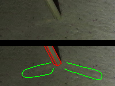
(Tangent) I'm not certain why I'm trying to persuade you, but here's a picture I just took:
Attachment:
 led_lead_corners_and_reflections.JPG [ 22.98 KiB | Viewed 3554 times ]
Top is the original (albeit with the wrong gamma to make the reflection show better), bottom shows the edges (in red) and the reflections off the faces (surrounded in green).
The first two random LEDs in T-1 or T-1¾ packages that I find on digikey indicate a square-ish lead cross-section, too:
this one indicates a rectangular cross-section of 0.4mm x 0.45mm and
this one indicates a cross-section of 0.5mm square.
Huh, you're right. I just checked my parts drawer and it's about 50-50 round lead and square lead. Guess I just hadn't noticed before.
Pasghetti wrote:
Would [a wire wrap tool] also be used for wrapping the wire around the bent up input pins?
I personally would have done it that way, but there isn't really a wrong way. Whatever you're most comfortable with.
If you hadn't clipped it, the wrap tool would've worked well, but one thing to mention is that you would want to clean the pin well with desoldering braid or else just by heating up the pin and wiping it off (both sides) with a wet sponge, because wire wrapping doesn't mix well with uneven solder deposits like you get when you pull a chip without cleaning the pin. Sometimes the tool will get caught or the wire will break, or other stuff. But as you said, it's clipped, so that's not an option, but you can just solder to the wide portion of the pin just fine.
Sounds good. I will de-solder the wires today, clean everything up with the braid, and start over again with the wiring. I am grateful that this is still an active and helpful community.
You don't really need to clean off the solder if you're going to be soldering to it, just if you're wire wrapping. If you're soldering, then there's no problem leaving the old solder there, the only downside is sometimes old solder doesn't flow very well, but even then just adding some new solder on top of it is usually sufficient.
I got it working!! Woo! All I had to do was repair one of the crappier wires after I did the continuity check. Now all I have to do is design an Earthbound label (:
Please tell me
The Legend of Zelda: Time Crisis isn't a
Zelda-themed Zapper game. How would you even make a Guncon for NES? Controller on bit 0 and Zapper on bits 3 and 4?