So I found out the hard way that a tlsrom (Mapper 118) board does not behave the same as a tlrom (mapper 4) board. They both contain a mmc3 mapper though.
I did not catch the mapper 118 in the beginning, I was only looking at the mmc3.
In my searching I have found this.
"The CHR A17 line connects directly to CIRAM A10 line instead of MMC3's CIRAM A10 output, to compensate for the MMC3's lack of single-screen mirroring"
http://wiki.nesdev.com/w/index.php/INES_Mapper_118
I seem to be missing something as I have traced these lines and they do not appear to be directly connected. I even do a continuity test on the 2 and nothing.
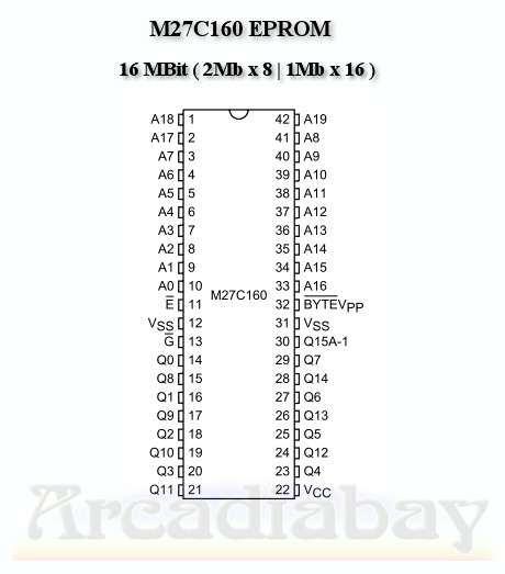
I have used this document for the mapper pinouts.
http://nesdev.icequake.net/rom.txt
I assume when looking at the mapper and the lettering right side up on lower left is a circle in chip corner that that marks pin 1. So according to what I am reading mapper pin 12 should have a direct connection to mapper pin 4 but they don't have continuity.
This is driving me insane. Maybe this board can't be used.
I did not catch the mapper 118 in the beginning, I was only looking at the mmc3.
In my searching I have found this.
"The CHR A17 line connects directly to CIRAM A10 line instead of MMC3's CIRAM A10 output, to compensate for the MMC3's lack of single-screen mirroring"
http://wiki.nesdev.com/w/index.php/INES_Mapper_118
I seem to be missing something as I have traced these lines and they do not appear to be directly connected. I even do a continuity test on the 2 and nothing.
I have used this document for the mapper pinouts.
http://nesdev.icequake.net/rom.txt
I assume when looking at the mapper and the lettering right side up on lower left is a circle in chip corner that that marks pin 1. So according to what I am reading mapper pin 12 should have a direct connection to mapper pin 4 but they don't have continuity.
This is driving me insane. Maybe this board can't be used.