The following are WIP screenshots of a VRC2/4 test program. All three screenshots are the exact same ROM with different iNES headers, running in FCEUX current SVN (r3372).
Briefly, the test program probes the connections of pins 3, 4 and 21 by writing values to $B0xx and then reading from CHR ROM via $2007 to see which CHR banks got switched in. Once it has determined the pin connections (and therefore what addresses to use to write to each mapper register) it tests the VRC4-specific capabilities: one-screen mirroring, swapping PRG $C000 instead of $8000, and IRQs (I'm currently working on the IRQ tests). After it has tested everything, it will display the ASIC type (VRC2 or VRC4), the PCB name that matches the results if one can be found (or "LEGACY EMU" if the results match an iNES mapper but not a specific PCB), and the iNES mapper number and NES 2.0 submapper number if any. Results are colour-coded: green for PCB-accurate behaviour, amber for legacy emulation behaviour (e.g. multiple address lines ORed together), and red for errors. However, the colour-coding is intended to be non-essential to interpreting the results.
I'd just like to make sure I'm on the right track here. Are there any suggestions for improvement?
Attachment:
File comment: Test ROM with mapper 21 header
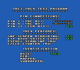
vrctest21-0.png [ 4.55 KiB | Viewed 11925 times ]
vrctest21-0.png [ 4.55 KiB | Viewed 11925 times ]
Attachment:
File comment: Test ROM with mapper 22 header
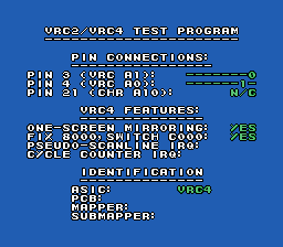
vrctest22-0.png [ 4.47 KiB | Viewed 11925 times ]
vrctest22-0.png [ 4.47 KiB | Viewed 11925 times ]
Attachment:
File comment: Test ROM with mapper 4 header (not VRC2/4; probing fails)
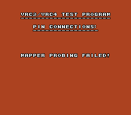
vrctest4-0.png [ 1.91 KiB | Viewed 11925 times ]
vrctest4-0.png [ 1.91 KiB | Viewed 11925 times ]
Briefly, the test program probes the connections of pins 3, 4 and 21 by writing values to $B0xx and then reading from CHR ROM via $2007 to see which CHR banks got switched in. Once it has determined the pin connections (and therefore what addresses to use to write to each mapper register) it tests the VRC4-specific capabilities: one-screen mirroring, swapping PRG $C000 instead of $8000, and IRQs (I'm currently working on the IRQ tests). After it has tested everything, it will display the ASIC type (VRC2 or VRC4), the PCB name that matches the results if one can be found (or "LEGACY EMU" if the results match an iNES mapper but not a specific PCB), and the iNES mapper number and NES 2.0 submapper number if any. Results are colour-coded: green for PCB-accurate behaviour, amber for legacy emulation behaviour (e.g. multiple address lines ORed together), and red for errors. However, the colour-coding is intended to be non-essential to interpreting the results.
I'd just like to make sure I'm on the right track here. Are there any suggestions for improvement?