Hope I'm not bothering anyone from obsessing about this now.

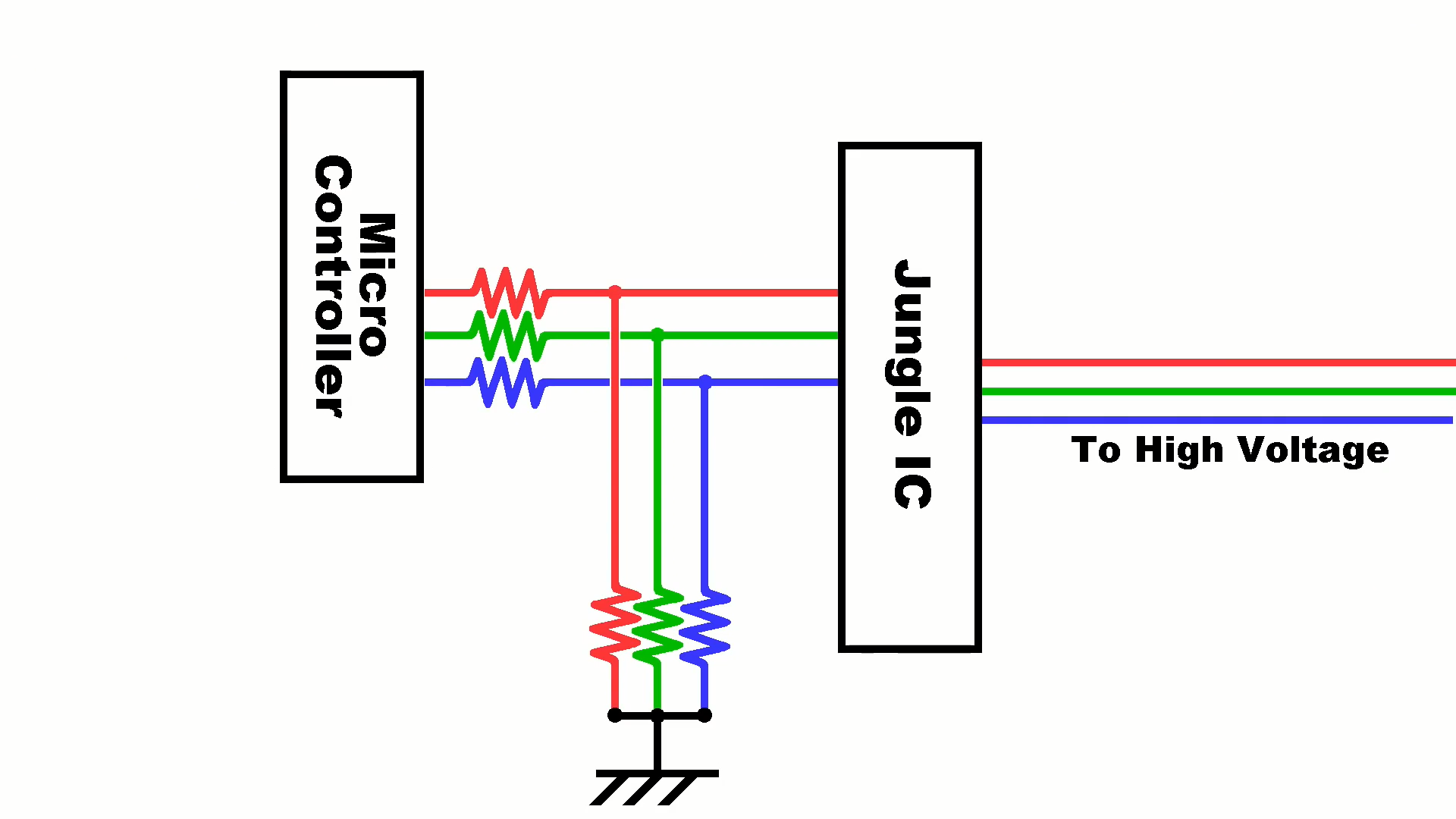
I had showed a video a while back ago where a CRT TV was modded to accept RGB input by tapping into the lines going to the jungle IC, but would have the side effect of blending the onscreen display with the image rather than overwriting it. Mods showcased in other videos I've seen didn't even do that; they just used a switch to select whether information from either the microcontroller or the RGB input went to the jungle chip.
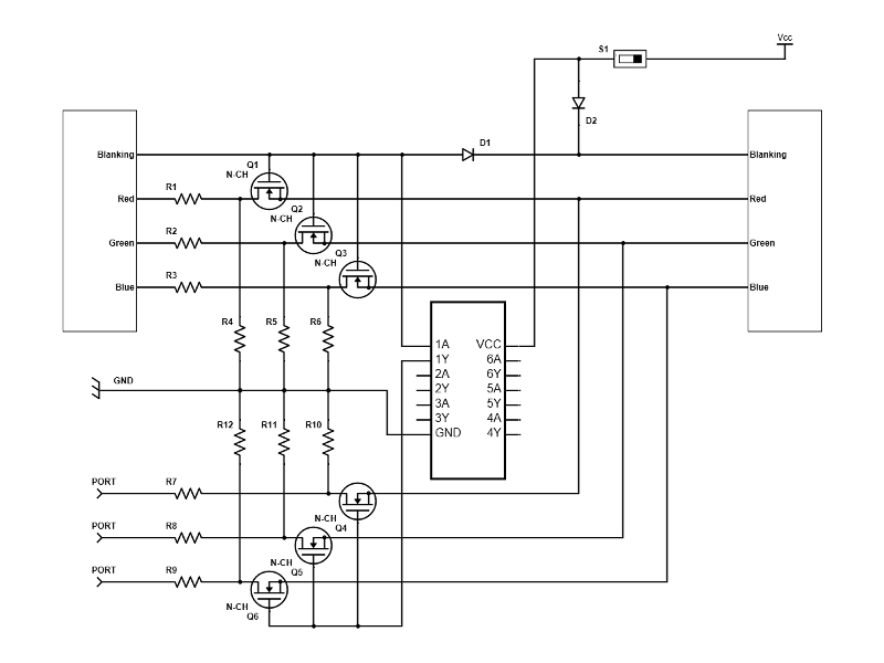
While definitely not the most practical solution because it requires a lot of extra parts, I was wondering if you could have the onscreen display "overlay" the RGB input by using MOSFETs, where whether or not the microcontroller is generating a blanking signal determines whether the signals from either the microcontroller or the RGB input are sent to the jungle chip.
Here's the awful schematic I made; if anything it at least better represents what I'm trying to say, because I know it's riddled with flaws. Basically, there's a transistor for each color element for both the microcontroller and the RGB input. That chip in the middle is a hex inverter that will invert whatever the blanking signal outputted from the microcontroller is for the RGB input transistors so that if that if microcontroller blanking is on, microcontroller RGB is passes through while RGB input does not and vice versa. The switch determines both whether blanking is on permanently or not as well as if the hex inverter gets power, the later of which I just now realized shouldn't really make a difference and that the hex inverter VCC wire could be put before the switch and the second diode removed... I guess you can save whatever electricity it takes to power the IC when not in RGB input mode
Attachment:
 New.png [ 12.38 KiB | Viewed 3777 times ]
I'll be honest, I didn't really know what I was doing with the resistors but thought I might as well leave them in... A big problem I have is that I don't understand what the three lines going to ground were for in this:
Attachment:
 Old.png [ 168.94 KiB | Viewed 3777 times ]
The explanation in the video is that they're for lowering the voltage, but the three resistors from the microcontroller should have done that anyway.
You're basically describing an analog multiplexer. Yes, that works.... but....
Your control signal has some problems. Does BLANKING actually indicate what you want it to? What pulls BLANKING down after your diode OR?
If the switch is open, for blanking, the jungle chip would pull it down, and if the switch is closed, the hex inverter would pull it down (now I remembered why I wired the hex inverter the way I did..). Or at least that's what I expect / hope...
Can't leave the inverter unpowered... you'll end up powering it via its overvoltage protection diodes if you do.
Right now, the overlay can pull the jungle chip signal high via D1, and the switch can pull the jungle chip signal high via D2, but what pulls the signal low?
I'm not sure I get the question, because I'm not sure I know what "pulling low" means... If you mean when does the jungle chip get logic 0, it would be the same as normal for when the switch is off, and never when the switch is on.
ok, let's just say: the circuit you have right now will cause the jungle chip to see logic high (+5v, "1") whenever the switch is closed OR the microcontroller drives BLANKING high.
But when the switch is open and the microcontroller drives BLANKING low ... the jungle chip will see any random thing because nothing causes the voltage on its input to drop.*
* Yes, technically diodes are very large resistors when reverse-biased, but the amount of time it will take for that to happen will be annoyingly long
Wait, I think I get it? Does no current actually go through blanking on the jungle chip?
Yeah, everything after ... eh, 1990? is purely voltage-based logic, almost never current-based.
edit: ... But even when it was current-based, your diodes are pointing the wrong direction. In 74LS logic, you get diode ANDs for free, not diode ORs.
After going back at this with more knowledge, I'm pretty sure that initial schematic is wrong in about 100 different ways. What determines if current flows through the NMOS transistor is not just voltage is applied at the gate, but that the gate voltage is higher than the source, which is why it's now connected to ground. If there's gate voltage (blanking logic 1), then the output voltage is 0V, which is the opposite of what's wanted, so the microcontroller RGB needs to be inverted instead of the input RGB. Testing this in Multisim shows that everything checks out (the switch controls is blanking is always on, the blanking voltage determines whether the output voltage is from the microcontroller or RGB input) but I'm pretty sure that there's no such thing as a giga Ohm resistor for something like this...
The higher the resistor value though, the closer the output is to the source voltage. Multisim also won't even try and emulate things like insane current blowing up the circuit or anything like that.
Attachment:
 Capture.GIF [ 43.12 KiB | Viewed 3561 times ]
Really, you just want an analog multiplexer. Something like a CD4053 will be more than adequate. Use it to select between the analog external input, or the voltage divider from the TV's OSD outputs (which are almost certainly 5V digital RGB)
Wow, you're right; it even has the exact number of inputs and outputs too. I'm surprised seemingly no one has done this given the IC is priced at less than a dollar.
I mean, the only instance we've seen widely of this hack is "The 8 bit Guy"'s video, right? There's too small of a sample size to say anything about what do people actually do.
Plus even if it's a $1 IC, it's a $1 IC that you probably don't already have on hand.
I saw about 4 other significantly less popular videos that either did the same thing or just forgot about mixing the signal altogether and removed the OSD. Obviously it doesn't matter much either way.
Oh, here's another possible reason: The CRT in my house has only two RGB stages: 8Vpp and 80Vpp. Can't trivially sub in 0.7Vpp in without adding a lot of circuitry.
This CD4053B data sheet seems to suggest that it will take analog signals of up to 20V though:
http://www.ti.com/product/CD4053B
Oh, sure, that's not the problem. The problem is that I don't have an external source that emits 8Vpp video. (That's not a standard at all. JAMMA uses 5Vpp, and that's the highest analog video range I know of)
Oh, okay. None of the other mods should have worked then either though. I do feel that something for changing the magnitude of the voltage would be external though anyway; you said JAMMA is 5Vpp, but what's SCART RGB?
Edit: looks like SCART RGB is 1Vpp. I guess the mod showcased in the 8-Bit Guy video is only working for SCART and not JAMMA.
Converting voltages down is easy: resistor dividers aren't a problem. It's just six resistors (three if you don't have to worry about matching cable impedance) to convert JAMMA 5Vpp analog down to 75Ω 0.7Vpp or 1Vpp.
As a complicating factor, the output impedance of the JAMMA board may be sizeable:
this example had such a high output impedance that it was only capable of sourcing ≈10mA into the 75Ω input impedance of the monitor anyway.
Officially, JAMMA
doesn't have to emit the correct analog video voltages into anything less than 1kΩ. I suppose if you do have to start adding current buffers for that situation, the other voltage and/or current scaling problems are comparable.
Aren't operation amplifiers used for increasing voltage? Sounds like by several magnitudes though, which obviously isn't ideal. And I didn't think a signal could have an impedance value... Unless you mean to say that, for example, a 6V 3Ω signal is a 6V 2A one.
Also, what TV do you have? 8Vpp just seems bizzare...
Every amplifying device as a "gain-bandwidth"; with a desired component bandwidth of somewhere around 14MHz and a gain of 11 needed, that requires something with a gain-bandwidth of 150 (or so). Furthermore, these signals need to be able to directly drive the final BJTs that drive the tubes themselves, so need to be able to source a lot of current.
Op-amps with that much bandwidth are not cheap.
A design that used a bunch of BJTs would work, but then you have the complication of needing to design something with rail-to-rail support.
Outputs, inputs, and cables have an impedance. In the case of cable, it's a fundamental rule of physics. In the case of outputs and inputs it's how "
non-ideal" it is—even if it is there to
prevent reflections.
From what little I've been able to tell, signals in the range of 8 to 20 Vpp are fairly typical on this final stage before the power transistors that drive the electron guns.
The TV here doesn't have separate "jungle" and OSD chips; the only place RGB component exists is on the output of the all-in-one chip.
Sorry if I'm being paranoid at this point, but about what year was your TV made? I'm wondering if the combination chip is typically found in newer CRTs.
Yeah, it's one of the last CRT TVs to be manufactured. 2006.
Yeah, shoot, both of mine are from about that period so they might not be eligible.
Mucking up service manuals for TVs without paying a scalper isn't too hard. (The problem with paying someone for a DL isn't the paying—although I resent that also. It's that you don't know if it's even useful until you already have it)
I figure I'll just open it up and look around; I presume it would be pretty obvious. I also imagine whatever chips being used will have part numbers written on them with a data sheet hopefully online somewhere. I wouldn't think a company would make new chips for every TV model?
What exactly is the TV you got ? elektrotanya has never failed me when finding any CRT service manual, new or old. Knowing the chassis number is the best way to get things going, it is often marked on the sticker on the back of the thing.
The chip where video comes out is usually the biggest one and the neck board wires will go near it. In worst case you only have its datasheet but more often that not the reference circuits in those are nearly same as what the device using the chip uses.
Drew Sebastino wrote:
I also imagine whatever chips being used will have part numbers written on them with a data sheet hopefully online somewhere. I wouldn't think a company would make new chips for every TV model?
New chips for
every model, no. New chips that never saw any release outside of CRTs and exclusively have in-house part numbers without any public documentation? Yes.
For example, the all-in-one in this TV is a "M61271M8-058FP" ... or 61371 ... or 61272 ... per the service manual. There's no information about it: only what you can infer from the service manual for the TV itself.
TµEE: my TV is a "sylvania" 6420FF; I can find the service manual for the 6420FE (previous generation?) and the 6427FF (same generation, larger tube) but not one for this specifically. But thanks for the pointer to elektrotanya!
Wow, that's a great resource! I found the TV I was interested in ("RCA" 204F24) but sure enough, it appears to have an all together chip. The only doubt I have is that there's a sync out; what is the neck board responsible for?
Neck board is usually just for driving the actual electron guns itself. If a "sync" signal goes to it it's probably a blanking signal to hide retrace lines.
Neck board is what amps that 4...8Vish RGB to 150ishV RGB to drive the cathodes.
Generally TV stuff all goes by "chassis" which is the term used for the electronics in the housing. One chassis is usually used in a selection of models, i.e Philips L04E chassis is used in some 10+ variations with varying sizes and the service manual for it will cover all those variations too. The chassis number is usually written on the sticker on back of the TV or sometimes on the board itself.
Sometimes those large chips belong to a single family of them, which has ton of part numbers due to different ROMs inside each chip. If you figured out the name of that family you could probably find some info out there. It only helps if these chips were not purely in-house stuff. Sony likes to have such chips that only their devices use, with no documentation about them available anywhere.