So I wanted to perform the AV modification on my Famicom. Google led me to a few different places with quick hacky mods and all of them seemed to have to deal with the jailbars and the infinite number of ways to possibly fix them. I decided to ask the master himself (kevtris) and get the best solution. He said to do it the way Nintendo did it. After searching for the NES schematics and checking them out, I began building my mod. After a few days of working and frustration, I got it working without the jailbar problem. It uses more components but the picture quality is nice. I have traced the NES schematics and included the relevant information in my attachment.
A little explanation about the schematic. First off, this is the first thing I have made with Eagle, I'm just learning it. The inductor is labelled as 'MISC15' and its value is 3.3uh. The three things on the left (H1, H2, and H3) are outputs from the Famicom. 5v, Pin 21 of the PPU, and Ground. The ones on the left (H4 and H5) are the leads going to your TV. All capacitors are ceramic.
Eagle has export scheme into the picture. There is no need to print screen.
Are you sure your R1 should be 510? according to the schematic I have it is 150.

I think there is supposed to be a 10µF electrolytic capacitor in between where the emitter of the left transistor (2SA937) meets a 330Ω resistor (negative side facing the transistor).
In simulation, the gain is entirely immune to a factor of 4 change on the value of R1. This makes sense, because it's a common-collector amplifier (voltage buffer) and the voltage above the transistor should be one diode drop above the voltage out of the PPU.
Let me begin by thanking you guys for your feedback, it is much appreciated.
The schematics I used was the buggy Electronix Corp ones for the NES-001. I do not doubt there are errors, but I have found using this method described works. The 10uf electrolytic capacitor right before the 330ohm resistor causes no video output, so I just omitted it. I do not know how it works. I haven't disassembled my NES (again) to check the schematic. Last night I traced the Twin Famicom's AV circuit, and I will be attempting it next. I have attached it here. D1 is mis-labeled because I cannot identify the diode part number.
As a suggestion you could go for the standard "hamburger"(as fast food style) kind of Schottky diode, "the legendary" 1N4148. That would be the "right diode" to use there.
So what I have done now was replace the power/RF board from the famicom with a new power supply and I have used the Twin Famicom AV circuit. I pulled my video directly from PPU pin 21. The picture is good. The diode I ended up using was a Panasonic MA2C029W. The characteristics seems to fit, and the diode looks just like the one in the Twin Famicom. More images can be found at
http://nesemu2.com/images/fammod/
deadbody wrote:
So I wanted to perform the AV modification on my Famicom. Google led me to a few different places with quick hacky mods and all of them seemed to have to deal with the jailbars and the infinite number of ways to possibly fix them. I decided to ask the master himself (kevtris) and get the best solution. He said to do it the way Nintendo did it. After searching for the NES schematics and checking them out, I began building my mod. After a few days of working and frustration, I got it working without the jailbar problem. It uses more components but the picture quality is nice. I have traced the NES schematics and included the relevant information in my attachment.
A little explanation about the schematic. First off, this is the first thing I have made with Eagle, I'm just learning it. The inductor is labelled as 'MISC15' and its value is 3.3uh. The three things on the left (H1, H2, and H3) are outputs from the Famicom. 5v, Pin 21 of the PPU, and Ground. The ones on the left (H4 and H5) are the leads going to your TV. All capacitors are ceramic.
Huge circuit, lots of filtering, blury picture as result.
80sFREAK wrote:
Huge circuit, lots of filtering, blurry picture as result.
What are you talking about? Any circuit that doesn't kill chroma in a composite signal isn't going to appreciably blur the luma.
Anyway, I tried his circuit in sim; it has no appreciable lowpass effect. The -3dB corner is at 100MHz.
No blurriness. Just some visible dot crawl. It was blurry because of some camera related problems. Here is some new pictures. Don't believe me? Build the circuit and see for yourself! I been running it on a 50-something inch LCD television.
The output looks identical to my twin famicoms video output. Same circuit same results. I decided to use this circuit instead of the "two resistor and a cap" circuits I've seen floating around the internet. This one has been tested and works on millions of televisions world-wide.
Also I would like to take this opportunity to thank the members of #nesdev. Without them I wouldn't be doing anything like this.
lidnariq wrote:
80sFREAK wrote:
Huge circuit, lots of filtering, blurry picture as result.
What are you talking about? Any circuit that doesn't kill chroma in a composite signal isn't going to appreciably blur the luma.
Anyway,
I tried his circuit in sim; it has no appreciable lowpass effect. The -3dB corner is at 100MHz.
Oh, good

Everything is on the last photo
Keep simulating and emulating, i've gotta go. All the best...
His pictures show far improved quality over your "correct" modifications shown on FW and substantially less jailbars. Are you dense?
I haven't seen 80sFREAK's pictures, but deadbody's mod lokos fine to me. The pictures are a little blurry, but thats just the photos I think. (Granted you'd need better pictures to accurately judge it)
Well I've had this thread bookmarked forever, and finally got around to performing the twin famicom video circuit mod to my original famicom. My primary motivation came from recently upgrading to a commodore 1702 monitor which lacks the RF tuner I made do with on my previous CRT.
Just wanted to share that this circuit worked great for me as well. For others looking to follow along, I also found some new transistors readily available from Digikey that worked well for me. I also used the 1N4148 as l_oliveira suggested.
Analog, video, and BJT's are far from my expertise, but I searched around and found the
KSA1015 has comparable specs to the 2SA1015, and it's compliment
KSA1815 looked comparable to the 2SC1740.
Also, just to shed some light on required audio modifications to go along with the video. No circuitry is needed, just need to tap from the cartridge audio output directly from the
60pin connector. So that ends up being cartridge pin 46.
Here's some pictures of my install. My goal was minimal intrusion to the console. I favor a modification that can be easily reversed with minimal signs that anything had been touched. Making the console appear that it was designed with AV out was not my goal.. The idea of taking a knife to my famicom makes me cry..
Thinking about picking up some tiny coax to replace my ribbon cables and cheapo RCA connectors, was all I had on had and good enough for now!
infiniteneslives wrote:
Well I've had this thread bookmarked forever, and finally got around to performing the twin famicom video circuit mod to my original famicom.
Hi, friend! I've recently started collecting parts for this specific twin-circuit, can you take a look, please, if it fits?
1N4148 DO-35 switching signal Doide
2SC1740 C1740
A1015 2SA1015 0.15A/50V PNP TO-92 DIP
Panasonic FM Series Capacitor Low Impedance (25v, 220uf)
I haven't done my homework regarding the resistors yet, can you suggest what kind suits best here?
ThePunisher wrote:
I haven't done my homework regarding the resistors yet, can you suggest what kind suits best here?
Your selections look fine to me at a glance. There's nothing special about the resistors.. Just get the suggested values in carbon film and you should be fine.
infiniteneslives wrote:
ThePunisher wrote:
I haven't done my homework regarding the resistors yet, can you suggest what kind suits best here?
Your selections look fine to me at a glance. There's nothing special about the resistors.. Just get the suggested values in carbon film and you should be fine.
Thanks alot, friend! I will post a video of gameplay, once all the parts arrive, and I'm done with soldering.
infiniteneslives wrote:
ThePunisher wrote:
I haven't done my homework regarding the resistors yet, can you suggest what kind suits best here?
Your selections look fine to me at a glance. There's nothing special about the resistors.. Just get the suggested values in carbon film and you should be fine.
Btw, the resistor values, described in the screenshot are regular ohm, right? Not kilo- or micro- ?
infiniteneslives wrote:
Correct.
Hi, once more I need to consult with you:
Where did you take the Ground? 80sFreak was very specific about it "Take ground from pin20 PPU. Don't ask why, just do it."
Did you lift the leg of PPU or just cut the pcb route? I really want to keep PPU untouched.
What kind of wire did you use? Shielded? Single vein?
I wouldn't lift any pins from the PPU if it were my famicom. Maybe it would help remove some of the jail bars if I did though..?
You can see where I took ground in my pictures. I just took it from the most convenient location. You can also see I just used cheapo IDE style ribbon cable.
These choices prob aren't the best ones. They were just what I had and met my desires just fine. Feel free to experiment!
My speculation about the use of pin 20 in particular:
PPU pins 40 and 20 are the PPU's power and ground pins, connected to the bypass capacitor nearest the PPU. I guess taking ground close to the PPU avoids ground loops and unwanted coupling.
Can I ask, the very specific values on two of the resistors - would an approximation work? Something like 75 ohm? I've never seen a 68 ohm resistor, but I could wire together some smaller resistors in series if that's the absolute desired resistance. I would have thought 75 would be within tolerance tbh.
68 and 82 are standard
E24 size resistors. 75Ω isn't.
75Ω is actually a little too big, because the voltage follower T2 has some small finite effective output impedance, and using a 75Ω resistor would generate an unmatched transmission line.
That's interesting.
Will I get a better video signal if I mod this circuit to be more like the suggested?
Attachment:
 GRADIENTE PHANTOM SYSTEM vout.jpg [ 31.93 KiB | Viewed 8277 times ]
They're pretty similar...
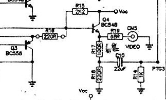
PTG3 goes to the RF modulator.
Can someone help me out here? Everything seems to be good up until the capacitor. I get ~4v DC going into the anode, then the multimeter quickly runs down to 0v at the cathode.
This is the second circuit I've put together now without success, so I'm either repeating a mistake, or there's something wrong. Should I be getting 4v before that cap?
*Edit* I've just measured without the RCA jack connected to the TV, and I get voltage, then with it connected, same as before.
I'm thinking this implies that the resistance the other direction is insufficient?
*Edit 2* also, I've taken ground from the regulator. I'd still.expect to see a signal though
Ok, I'm dumb, that's how it's supposed to work. Hmm, no signal though. I'm reading (from memory) something like 0.06V AC at the cap and to the RCA jack. Could be a bad PPU since it's untested, but hard to tell without an oscilloscope.
Seems like i need to try this out. Is there any recommended good point to add variable resistor for brightness adjustment?
infiniteneslives wrote:
Well I've had this thread bookmarked forever, and finally got around to performing the twin famicom video circuit mod to my original famicom. My primary motivation came from recently upgrading to a commodore 1702 monitor which lacks the RF tuner I made do with on my previous CRT.
Just wanted to share that this circuit worked great for me as well. For others looking to follow along, I also found some new transistors readily available from Digikey that worked well for me. I also used the 1N4148 as l_oliveira suggested.
Analog, video, and BJT's are far from my expertise, but I searched around and found the
KSA1015 has comparable specs to the 2SA1015, and it's compliment
KSA1815 looked comparable to the 2SC1740.
Also, just to shed some light on required audio modifications to go along with the video. No circuitry is needed, just need to tap from the cartridge audio output directly from the
60pin connector. So that ends up being cartridge pin 46.
Here's some pictures of my install. My goal was minimal intrusion to the console. I favor a modification that can be easily reversed with minimal signs that anything had been touched. Making the console appear that it was designed with AV out was not my goal.. The idea of taking a knife to my famicom makes me cry..
Thinking about picking up some tiny coax to replace my ribbon cables and cheapo RCA connectors, was all I had on had and good enough for now!
Hello this mod looks very clean congratulations! I am trying to do this mod to a Famiclone from the late 80s early 90s, I already have the circuit built based on the schematic that was posted by deadbody, but I have a question that hopefully you can help with, since the PCB on this clone is not 100% the same I need to ask you what are the 3 cables at the middle of the PCB? I assume its GND (the one with the red mark), 5V and (pin 21) AV OUT, correct?
Thanks!
Ok, so.. I've had this going off and on for a few years, but I've never managed to get it working. It's taught me quite a bit, but I'm still not there.
I've lifted pin 21 on the PPU, but aside from that, do I need to make any other modifications to the main console? Remove transistors etc? Or can I just take the output from the PPU and process it
*edit* hmm, ok I think part of the problem was that I tried taking power and ground straight from the 7805 regulator. I ended up replacing that anyway, but still no signal. Going to try moving the ground and power again, but I think the Famicom might be a dud. Getting closer though