I have a Twin Fami coming in the mail soon, and while I mod it for the NESRGB, I also plan to change out the power jack so I can use a model 1 Sega Genesis/SMS power supply. When I had a Turbo Twin Fami, I actually added such a power jack and it worked just fine using that particular PSU. However, what I'd really like to know is if doing such a thing on the original Twin Fami will be detrimental over time, or if the Twin Fami will be fine and dandy using a 9-10V PSU.
Oookay, so using a 10V PSU on a Twin Fami with an NESRGB installed wasn't necessarily a good idea. While playing Zelda on the FDS after 40 minutes or so, the screen started flickering and the disk drive started moving (!) even when unprompted to do so. The heat sink for the 2SB941 power transistor also got blistering hot so it wasn't exactly happy with 10V.
I've now ordered a good regulated universal PSU that outputs 7.5V so hopefully I won't have this problem again.
I've now ordered a good regulated universal PSU that outputs 7.5V so hopefully I won't have this problem again.
The voltage shouldn't matter as much as the current supplied by the adaptor. The Twin needs 1.25A (says on the adaptor) and that's just with the FDS+Fami (not including the NESRGB). How much current can your universal adaptor supply?
Although I can't actually tell whether this has anything to do with the supply voltage without seeing a schematic to know how the 2SB941 is wired, but if something's overheating, it's too much current through it or too much voltage across it. (Or it broke due to some other past abuse.)
ccovell wrote:
The voltage shouldn't matter as much as the current supplied by the adaptor. The Twin needs 1.25A (says on the adaptor) and that's just with the FDS+Fami (not including the NESRGB). How much current can your universal adaptor supply?
The new PSU I got puts out 1.5A, whereas the Genesis PSU I was using outputs 1.2A.
It looks I have a more serious problem on my hands now, the disk drive head won't stop moving and nothing except disconnecting it helps. Even having the cartridge mode selected does nothing.
EDIT: Did a little poking around and I think I've narrowed it down to the culprits. I'm thinking one of the logic chips on the power PCB (there's a 4001 and 4013) has failed or it could also be the 2C33. Thoughts?
EDIT: Did a little poking around and I think I've narrowed it down to the culprits. I'm thinking one of the logic chips on the power PCB (there's a 4001 and 4013) has failed or it could also be the 2C33. Thoughts?
Anyone?
The 4001 and 4013 are standard parts, so it's at least possible to replace them from new parts.
Do we have a schematic for the drive itself? It's hard to do any diagnosis with neither the hardware nor a schematic.
Do we have a schematic for the drive itself? It's hard to do any diagnosis with neither the hardware nor a schematic.
That's part of my problem, I can't seem to find jack shit for the FDS schematic-wise. All I know at this point is that the 2C33 commands the disk drive, which is why I'm listing it as a possible suspect. Really hoping that's not the case considering I'd have to cannibalize an FDS RAM adapter for one.
Is there only the one PCB in the drive itself? can you take it out non-destructively? If so, a picture of both sides of the PCB will give me the best ability to guess.
lidnariq wrote:
Is there only the one PCB in the drive itself? can you take it out non-destructively? If so, a picture of both sides of the PCB will give me the best ability to guess.
The drive is exactly the same as used in the FDS so it only has a single PCB inside with the drive controller chip and supporting circuitry.
So I remember finding a schematic of the RAM adapter itself: http://green.ap.teacup.com/junker/119.html
Are there any other places for logic besides the power PCB and the RAM adapter? Given the above schematic, I have no idea where this 4001 or 4013 you're mentioning is.
Are there any other places for logic besides the power PCB and the RAM adapter? Given the above schematic, I have no idea where this 4001 or 4013 you're mentioning is.
lidnariq wrote:
Given the above schematic, I have no idea where this 4001 or 4013 you're mentioning is.
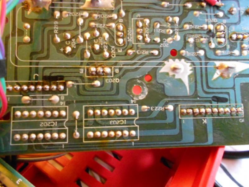
They're on the power PCB, right next to the power connector for the disk drive. Here's a picture along with another pic of the underside of the board:
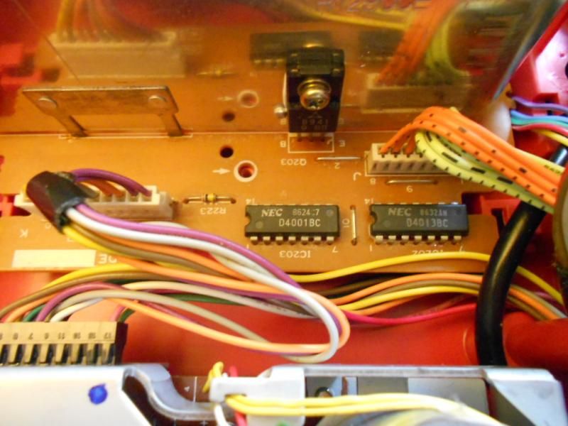
For some strange reason these chips are entirely omitted on the Turbo Twin Fami's power PCB, they're only present in the original Twin Fami.
EDIT: I've tried tracing out the power circuitry and it seems as though Sharp's engineers must've been taking some fairly strong drugs. Seems pretty overcomplicated for something that only puts out 5V.
So, I have no idea exactly what the NOR gates in the 4001, or the D latches in the 4013 are doing... mainly because I don't know what signals are on the cables going into the board.
Interestingly, this guy's Twin Famicom doesn't have the same board as yours: http://retrostuff.org/2012/12/23/disass ... n-famicom/
Between that and this: http://famicomworld.com/workshop/tech/f ... fications/ I bet your Twin Famicom has protection against rewriting the entire disk. I bet you could bypass them altogether...
Anyway, the signal that controls whether the drive spins doesn't look like it goes through the 4013 and 4025 in the ordinary Famicom FMD-POWER boards. So this seems more likely to be something fried in the 2C33? Given the schematic, the value written to the least significant bit of $4025 specifies whether the motor should be on or not. BUT if that's the only thing that's broken (not that I'd be certain it is), this is fixable by adding a little bit of hardware to reimplement the same functionality (four 74xx family ICs, I think). Do you have a logic tester or LED and a big resistor? It shouldn't be too hard to find out whether the FDS BIOS is successfully telling the 2C33 to drive that line high/low.
That said, there's also the PCB attached to the drive itself, with the FD3206P or FD7201P IC drive controller. It's possible that's screwing things up also (but once again, no schematic, so I don't know)
OK, so I looked at pins 49 and 50 (both related to $4025) of the 2C33 and they're both showing 5V meaning they're held high. Shit...
Well, it could be an input being wrong instead, if the BIOS does a drive seek on boot and never gets the "I'm done" signal.
Is there a possibility the drive controller is causing it? I can't find any pinout information for the FD7201 so I'm really grasping at straws right now.
Definitely plausible, but I can't find any information about the drive itself.
It looks like it should be really simple; most of the I/O from the 2C33 look like they ought to be directly connected to switches and things. What do the rest of pins 45-50 (i.e. $4032 in and $4025 out) read?
It looks like it should be really simple; most of the I/O from the 2C33 look like they ought to be directly connected to switches and things. What do the rest of pins 45-50 (i.e. $4032 in and $4025 out) read?
Pin 48 looks like it's held low, pin 47 is high (5V), 46 is also high and 45 is also held high. It looks like all of $4032 is held high then. And the strange thing is that despite all this, my disks still load perfectly fine and the BIOS also behaves fine; it responds when I press the various switches on the drive and doesn't do anything if there's no disk in the drive.
Wait, pin 48 ($4025.0) is the one that is specifying whether the motor should be spinning, and you say it's low. So the problem is not the 2C33 after all...
If you trace the signal, does it just connect to the drive itself, or does it go to the power board first?
If you trace the signal, does it just connect to the drive itself, or does it go to the power board first?
It goes right into the drive.
Hm. I'll bet it's actually the FD7201 that's toasty, then. Is the PCB that contains it single-sided? Does the signal from pin 48 go through the FD7201?... or is this the 2SB941 you were talking about in the very beginning?
If it is the same transistor, you should just be able to replace it.
If it is the same transistor, you should just be able to replace it.
lidnariq wrote:
Hm. I'll bet it's actually the FD7201 that's toasty, then. Is the PCB that contains it single-sided? Does the signal from pin 48 go through the FD7201?... or is this the 2SB941 you were talking about in the very beginning?
If it is the same transistor, you should just be able to replace it.
If it is the same transistor, you should just be able to replace it.
The 2SB941 is a TO220 transistor which is mounted on a giant heat sink on the power PCB. It seems to take the place of a normal voltage regulator, since it takes in the input voltage from the PSU and puts out both 5V and another voltage (which I think is used for the M5236L regulator, which then turns it into 5V). Why Sharp used this arrangement as opposed to two 7805s and a high amperage PSU I'll never understand. I actually desoldered it just to see if it went bad somehow, then I tested it with my multimeter and it checked out fine.
So I guess anything between 7.5 and 8V is the safe limit for the Twin Fami. I don't think having an NESRGB installed helped matters either considering it needs nearly 150 mA of current. That plus the additional load of the disk drive on a 10V PSU pushed the power transistor to its limits rather quickly I suppose.
Anyway, $4025.0 goes right into pin 11 on the drive controller so it looks like the FD7201 is the most likely culprit.
You might be able to bypass the motor driver part of the FD7201. I can't quite tell exactly what the on-drive PCB is doing, but it sounds like the motor driver is probably just the equivalent of a power darlington NPN transistor—after all, high voltage = spin motor. Might want a flyback diode, if there isn't already one.
The only picture I've been able to find are the ones on this page: http://famicomworld.com/workshop/tech/f ... write-mod/ which is hard to reverse engineer without seeing the other side.
The only picture I've been able to find are the ones on this page: http://famicomworld.com/workshop/tech/f ... write-mod/ which is hard to reverse engineer without seeing the other side.
I think I'll just go ahead and swap out the drive controller. Hopefully someone has a junked FDS drive that I can scavenge parts from...
Best of luck!
If you'd be willing to post a picture of the other side of the FD7201-containing-PCB I'd appreciate it.
If you'd be willing to post a picture of the other side of the FD7201-containing-PCB I'd appreciate it.
EDIT: Is there still any possibility that the two copy protection chips on the power PCB are causing issues? I'm planning on making a parts run soon to one of my local electronics shops and I figured maybe I'd try replacing the 4001 and 4013 just for grins, especially since they're common parts.
Well, I just did a thorough exam of the drive last night and I've determined that there is absolutely zero issue with the switches. I kinda had hope in the back of my mind that perhaps one of the switches got stuck, but they both look and work fine.
I didn't see your previous post after your edit. Sorry!
I doubt the 4000 series ICs could cause this particular flaw; my understanding is that they interfere with the "write requested" line, not the "motor spins" line. (obviously, documentation here is lacking, and without knowing what signals enter into both headers in your photos, I can only really go on hearsay)
Is the motor connected Vsupply—motor—FD7201? If so, it should be pretty easy to see if the relevant output pin is held low despite the 2C33 not requesting that. (A sustained slight overvoltage could have caused too much current to flow through the driver in the FD7201, blowing it out... in this case, apparently to "always on"). As I said before, you should be able to use a TIP120 power darlington or a a NTP60N60L power MOSFET or (although it's overkill) a L293D H-bridge driver.
lidnariq wrote:
I didn't see your previous post after your edit. Sorry!
Yeah, I edited my post because it turned out that the busted drive that was previously in my Twin is being refurbished; the drive that's in my Twin was actually pulled from a fully working FDS, and the old drive is going into that FDS once it's refurbed and that FDS will then be put up for sale.
The head still moves by itself and now I'm at a loss as to what to do next.
EDIT: It works!!! I wound up replacing the C311C voltage comparator and the 4560 op-amp, and it works perfectly again! This one frustrated me for quite a while and I'm very happy this finally got resolved.
Where are these parts?
lidnariq wrote:
Where are these parts?
They're located on the drive PCB.