I've owned a Good Boy GB-300SE console since 1996 with the TA-02NP and TA-03NP1 chip set. The audio quality on this machine has always been very distorted, so I tended not to use this console, instead using the Scorpion 8 console (T1818P chip) I bought at the same time.
However, the Scorpion 8 has the pulse wave duty cycle bug and is always 50 Hz PAL (converted NTSC hybrid), whereas the Good Boy does not have the bug and the TA-02NP PPU is 50 Hz / 60 Hz PAL switchable. So about a week ago I had a look to see if I could improve the Good Boy audio quality.
The Good Boy circuit has a common emitter voltage amplifier which varies in gain with the parameters of the transistor used (2SC945), and in the configuration in my Good Boy, is prone to clipping distortion.
The circuit also uses 1K pull down resistors for the audio outputs on the TA-03NP1 chip (pins 1 and 2). This produces a wide voltage range on the outputs but with a somewhat non-linear response. The DAC steps are closer together on the high values and further apart on the low values.
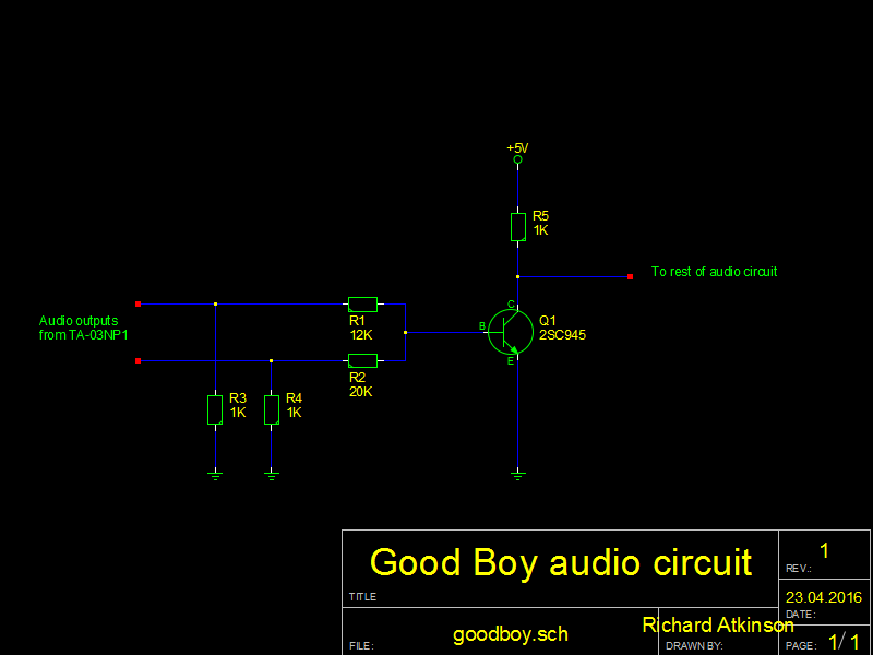
Good Boy audio circuit (original).png [ 13.33 KiB | Viewed 1434 times ]
I modified the circuit to remove the distortion and make the audio outputs from the TA-03NP1 chip more linear.
The new circuit uses 220R pull down resistors for the audio outputs and a 22R emitter resistor for the voltage amplifier to make the circuit more linear and the gain less dependent on the parameters of the transistor.
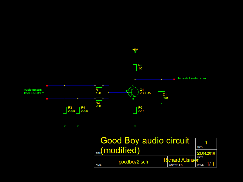
Good Boy audio circuit (modified).png [ 13.35 KiB | Viewed 1434 times ]
However, the Scorpion 8 has the pulse wave duty cycle bug and is always 50 Hz PAL (converted NTSC hybrid), whereas the Good Boy does not have the bug and the TA-02NP PPU is 50 Hz / 60 Hz PAL switchable. So about a week ago I had a look to see if I could improve the Good Boy audio quality.
The Good Boy circuit has a common emitter voltage amplifier which varies in gain with the parameters of the transistor used (2SC945), and in the configuration in my Good Boy, is prone to clipping distortion.
The circuit also uses 1K pull down resistors for the audio outputs on the TA-03NP1 chip (pins 1 and 2). This produces a wide voltage range on the outputs but with a somewhat non-linear response. The DAC steps are closer together on the high values and further apart on the low values.
Attachment:
Good Boy audio circuit (original).png [ 13.33 KiB | Viewed 1434 times ]
I modified the circuit to remove the distortion and make the audio outputs from the TA-03NP1 chip more linear.
The new circuit uses 220R pull down resistors for the audio outputs and a 22R emitter resistor for the voltage amplifier to make the circuit more linear and the gain less dependent on the parameters of the transistor.
Attachment:
Good Boy audio circuit (modified).png [ 13.35 KiB | Viewed 1434 times ]