Hello.
I recently tried overclocking my PAL NES with an LTC1799 Oscillator PCB Module. I will leave links to all the guides and information I found relating to this mod as I couldn't find a reliable guide or diagram which was clear in using this specific oscillator as a new clock
I have already cut off the original clock trace and I've checked it and all that.
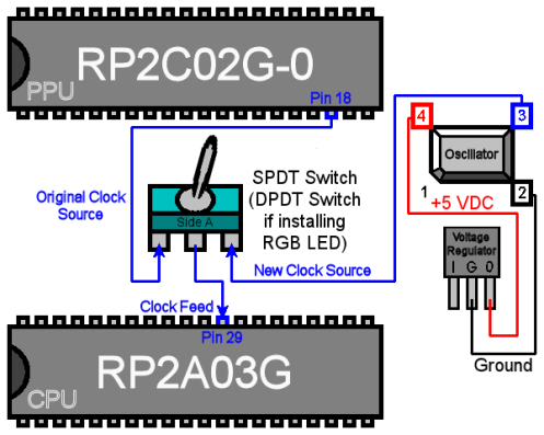
So the problem here is that I have a switch to change between the original PAL Clock which is slower, and the new one which can be adjusted with a variable resistor, frequency pot or potentiometer. Whatever you want to call it. While the old clock works 100% fine, boots up the game and runs as it should with the correct sound pitch, the new clock just stays as a blank red screen when you try to boot the console. When you flick the switch to the old clock, it begins running the game correctly, but once you try flicking the switch to the new clock the game freezes and the screen gets corrupted. You can turn the variable resistor and hear a frequency which changes in pitch as you turn the variable resistor but the game is frozen and I don't know how to fix it
In case it's important the frequency pot I've used is 250k. I don't know if that effects anything but if you're willing to take the time to look through and see what is wrong I'd be very grateful.
Here are all the links I've used as guidance and got information from:
Link 1: https://nobitleftbehind.wordpress.com/2014/07/28/how-to-overclock-the-nes/
Link 2: http://www.thejobbitt.com/nes-guides/nintendo-nes-001-overclocking-guide/
Link 3: http://furrtek.free.fr/?a=nesclock
Link 4: https://ancientelectronics.wordpress.com/tag/nes-overclock/
Link 5: http://www.circuitbenders.co.uk/forsale/LTC/LTCPCB.html
Link 6: http://www.getlofi.com/wp-content/uploads/2008/10/2_LTC_Instructions.jpg
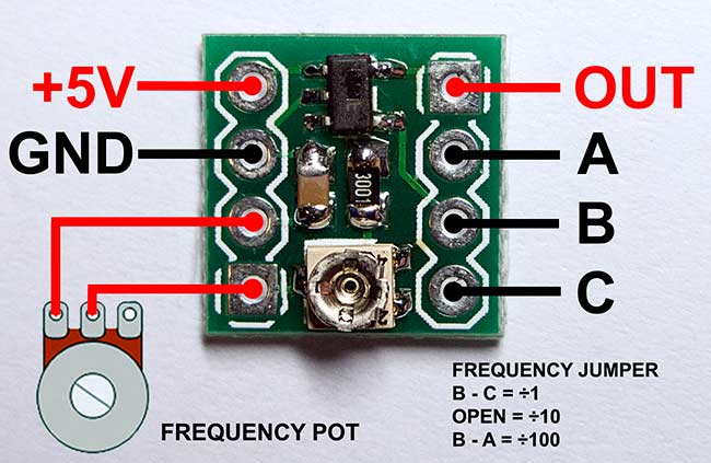
I basically followed Link 1's diagram but linked to Link 5's PCB Module with a variable resistor attached to the module to adjust the rate of frequency.
I recently tried overclocking my PAL NES with an LTC1799 Oscillator PCB Module. I will leave links to all the guides and information I found relating to this mod as I couldn't find a reliable guide or diagram which was clear in using this specific oscillator as a new clock
I have already cut off the original clock trace and I've checked it and all that.
So the problem here is that I have a switch to change between the original PAL Clock which is slower, and the new one which can be adjusted with a variable resistor, frequency pot or potentiometer. Whatever you want to call it. While the old clock works 100% fine, boots up the game and runs as it should with the correct sound pitch, the new clock just stays as a blank red screen when you try to boot the console. When you flick the switch to the old clock, it begins running the game correctly, but once you try flicking the switch to the new clock the game freezes and the screen gets corrupted. You can turn the variable resistor and hear a frequency which changes in pitch as you turn the variable resistor but the game is frozen and I don't know how to fix it
In case it's important the frequency pot I've used is 250k. I don't know if that effects anything but if you're willing to take the time to look through and see what is wrong I'd be very grateful.
Here are all the links I've used as guidance and got information from:
Link 1: https://nobitleftbehind.wordpress.com/2014/07/28/how-to-overclock-the-nes/
Link 2: http://www.thejobbitt.com/nes-guides/nintendo-nes-001-overclocking-guide/
Link 3: http://furrtek.free.fr/?a=nesclock
Link 4: https://ancientelectronics.wordpress.com/tag/nes-overclock/
Link 5: http://www.circuitbenders.co.uk/forsale/LTC/LTCPCB.html
Link 6: http://www.getlofi.com/wp-content/uploads/2008/10/2_LTC_Instructions.jpg
I basically followed Link 1's diagram but linked to Link 5's PCB Module with a variable resistor attached to the module to adjust the rate of frequency.