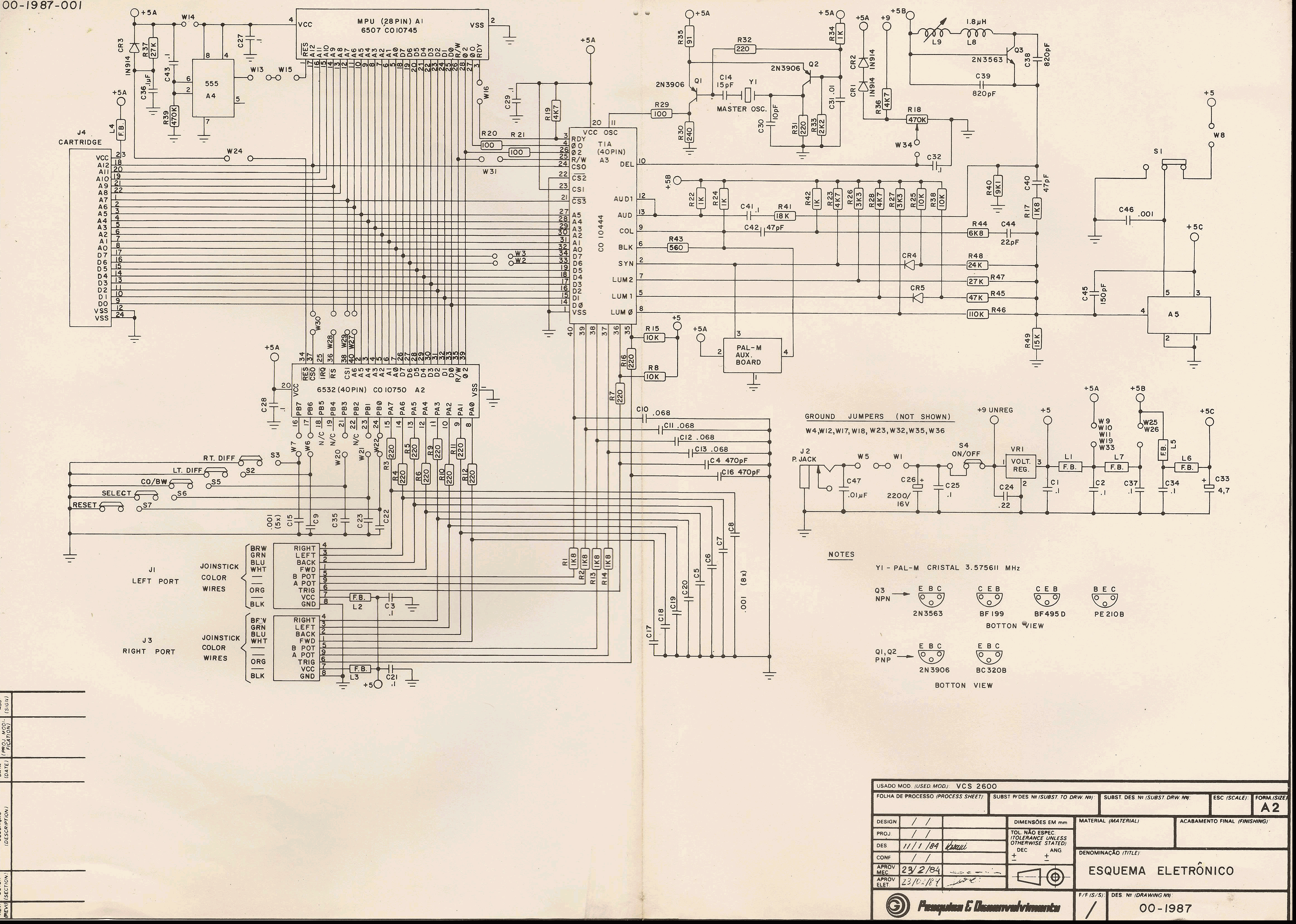
Hi.
I'm trying to fix an old
NES clone.It's almost fully functional, but I still could not fix the power button.
I tried to draw the schematic and end with this:
Attachment:
File comment: Phantom System power switch
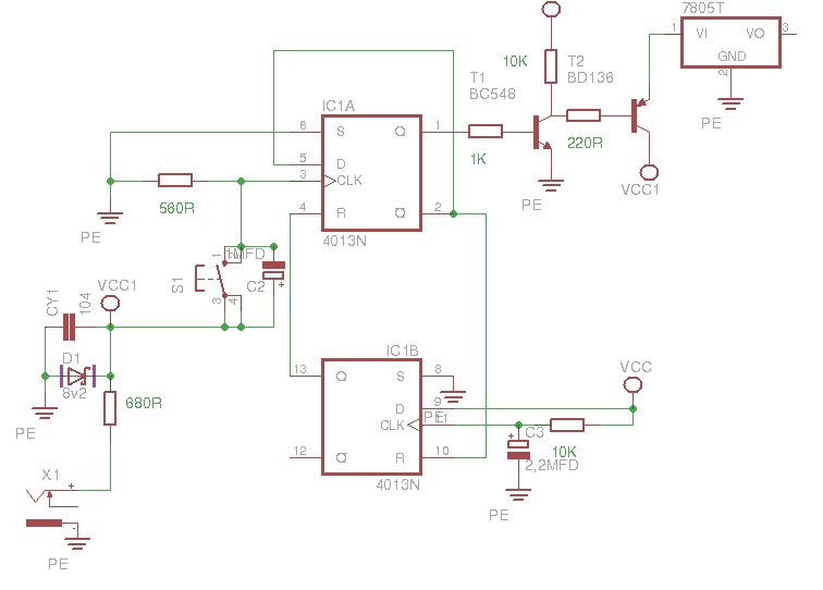 4013 Toggle.png [ 9.38 KiB | Viewed 5849 times ]
Probably has some mistakes...

I've already exchanged both transistors and the 4013. No deal.
I measured the resistors and they look fine, also the zener diode.
Maybe I should adapt another power switch...

Does someone have the full schematics for this clone?
Looks like I also have an bad 74'368 since I'm having trouble with the second controller, only A button works and it is read like A+B+Start+Left.
Thanks in advance.
Fisher wrote:
Probably has some mistakes...
Eh, the schematic is pretty close to plausible as is.
* Is the 680Ω resistor in series with the plug the only way to get power into the device? It's too big for the typical power consumption of the 2A03/2C02 (which is about 400mA), so I assume it's too big for the clone ICs used here.
* T2's collector and emitter are backwards.
Where does VCC come from? (VCC1?)
The bottom half of the 4013 prevents the soft button from working for the first 22ms after power is plugged in. The top half is what actually controls the output.
Quote:
I've already exchanged both transistors and the 4013. No deal.
What test equipment do you have access to? (BJT tester? 'scope? voltmeter?)
I'd just want to make sure simple things like:
* is pin 4 actually 0V like it should be after the first 22ms?
* is pin 3 high (8.2V) while the momentary button is pressed, and 0V later?
* do pins 1, 2, and 5 toggle when the momentary button are pressed?
Everything here should be low enough bandwidth you could even get away with using a soundcard as a 'scope — just make sure that you include some overvoltage protection & current limiting before plugging anything into your computer.
Quote:
Looks like I also have an bad 74'368 since I'm having trouble with the second controller, only A button works and it is read like A+B+Start+Left.
That sounds more like the controller is damaged, than that the 74'368 is.
Corrected the schematics.
Not sure if there are more mistakes...
Does it makes better sense?
Attachment:
File comment: New toggle
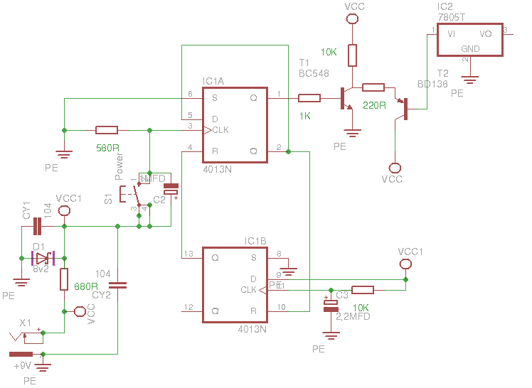 4013 Toggle.png [ 10.86 KiB | Viewed 5818 times ]
Could this work without the 2nd flip-flop?
It's a little difficult to trace, since the board has some damage and a little oxidation...
The schematics would make things clear if I could get it.
I only have a simple multmeter that measures resistense, AC and DC volts and some amperage.
I'm trying to find a proper socket to use on the IC.
As soon as I put it back I'll check these voltages.
Thanks for the tips

I also tought it was the controller, but I swapped them and got the same results.
Maybe it's some damaged trace or connector?
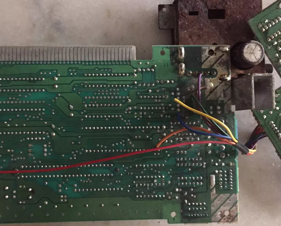
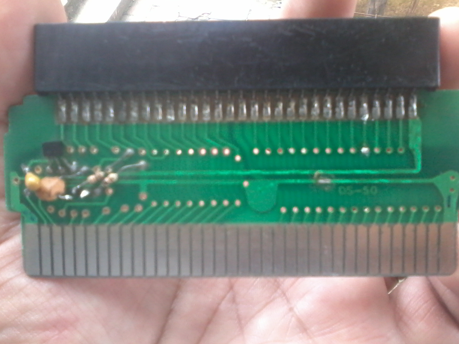
I tried to draw the joystick 2's output circuit.
Here is player 2's 9 pin connector as from under the board, with the 10k resistors omitted:
Code:
IC-8, 12<------| |-----> IC-8, 6
| |
IC-8, 10 <--O O O O--> CPU, 38
GND <-----O O O O O----> VCC
IC-8, 15 <---| | |-------> IC-8, 2
\/
CPU 39
Code:
IC-8 74HC368
.--\/--.
CPU Pin 35 |01 16| VCC
Controller Pin 4 |02 15| Controller Pin 2
CPU Pin 28 |03 14| CPU Pin 30
? |04 13| ?
CPU Pin 27 |05 12| Controller Pin 7
Controller Pin 8 |06 11| CPU Pin 24
CPU Pin 26 |07 10| Controller Pin 6
GND |08 09| CPU Pin 25
`------´
Maybe if I redo the traces to CPU pins 35, 28, 30 and 39 fix the issue.
I had a huge problem with some VRAM traces that when touched made continuity...
Maybe this can be the same case?
Fisher wrote:
Corrected the schematics.
You swapped the base and collector on T2 instead of the collector and emitter.
I suspect it should look more like
Code:
Vcc
|
v
|/
-220-|
|/ |\
Q ]-1k-| ---[ 7805 IN
|\
v
gnd
The 10k resistor shouldn't be necessary, even though I believe it's present.
(When pin1 Q is high, current flows through the NPN BJT from the base to the emitter, causing current to flow from Vcc via the PNP from the emitter to the base to the NPN's collector; allowing current to flow through the PNP from the emitter to the collector)
Quote:
Could this work without the 2nd flip-flop?
The bottom half? Probably. As I said, it's there to make sure that the famiclone starts powered off, and that you can't power it up before the capacitors have had some time to charge.
Quote:
I also tought it was the controller, but I swapped them and got the same results.
Maybe I misunderstood what you meant?
I thought what you meant was "if you press any of A, B, Start, or Left, the game thinks the A button is pressed" ?
But maybe you meant the opposite, that "if you press the A button, the game thinks all buttons are pressed". If so, that indicates that either the LATCH signal (
"OUT") or the SHIFT signal ("CLK") aren't making it through.
Hopefully now it should be correct:
Attachment:
File comment: Toggle rev2
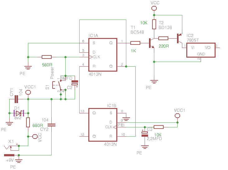 4013 Toggle.png [ 10.55 KiB | Viewed 5768 times ]
I soldered the socket on the board.
It was very weird, I checked the tensions and all were no bigger than 1.3v, even at the zener.
I removed the IC from the socket and the zener tension went normal.
Fortunatelly, I had found another 4013 on the junk pile, and it worked!
Looks like that was it!! Thanks!

Now I'm having trouble with the push button.
The ones I got became around 150 Ohms when pressed.
Can this circuit be easily modified to accept this kind of push button?
Quote:
But maybe you meant the opposite, that "if you press the A button, the game thinks all buttons are pressed".
O yeah! That was what I meant to tell. Damm language barrier!!
I also socketed the player 2's IC, switched it and no deal

It keeps the same problem...
I tested the outputs and all passed the continuty tests...
The Zapper also don't works.
Fisher wrote:
Now I'm having trouble with the push button.
The ones I got became around 150 Ohms when pressed.
Can this circuit be easily modified to accept this kind of push button?
Sure. Increase the 560Ω resistor until it works reliably, decreasing the 1µF capacitor proportionately. (i.e. preserve the RC time constant somewhere vaguely near 560µs)
Quote:
I tested the outputs and all passed the continuty tests...
Check for capacitive load, possibly parasitic. The CLK signal is only low for for ≈560ns, so it's easy for that to get too blurred.
Quote:
The Zapper also doesn't work.
I assume you already checked that 4017D3 and 4017D4 go through cleanly?
Great! Thanks for the info!
I tried some R/C combinations and the one that worked fine was 1M/47pf isn't that too much?
On the joystick I noticed that the buffer's pin 1 should be connected to pin 15, wich wasn't happening.
A bridge solved the problem.
Shouldn't M2 be present on the joystick port through the buffers?
I couldn't find any connection to it.
1MΩ+47pF seems ridiculous, but if it's reliable, then sure, whatever: the 4013 is a CMOS part so has approximately no input current.
In the Famicom, M2 and /RD4016 are combined to produce a signal that should be
* Driven high during not-M2 of a cycle when reading from $4016
* Driven low during M2 of a cycle when reading from $4016
* External weak pullup the rest of the time.
In the NES, it tentatively looks like /RD4016 just goes directly to the controller jack instead.
Tangent: this should mean that the DPCM controller glitch should cause only one bit deletion on NES decks, but multiple bit deletions on original HVC-001 Famicoms.
Yes. It's working just fine.
Thanks again for all the help!!

Interesting, /OE2 goes to controller port and the buffer.
If I understood right, it's what enables the buffer.
There's still an umpopulated part on the board.
Since it's plugged on the PPU it may be someting related to the composite video transcodification.
In this board I have an UM6528 PPU, the colors seem a little differen from the UM6548.
Or maybe it's the output circuit or board layout that gives diferent colors.
It still have very noticeable jailbars... on the other clone I removed the video buffer form the board and soldered directly on the PPU, then used a coax I got from an old notebook wifi antenna. It's almost unoticiable now!
I found very strange that it has an audio and video output on the cartridge slot!!
Many thanks man!!
You rock!!
Oops...
Looks like I totally miscalculated the capacitor!
It should be 560 pf for the 1M resistor. Correct?
Should I exchange It?
I mean, won't this make the circuit work out of spec and lead to problems in the future?
I also have some doubts about transcodification, but I think I 'll ask it in other thread.
Fisher wrote:
It should be 560 pf for the 1M resistor. Correct?
Yes, but...
Quote:
Should I exchange It?
If it works, it works. Unless you're noticing problems with button bounce (e.g. sometimes you press the button and the clone stays on or stays off), I wouldn't worry about it.
Quote:
I mean, won't this make the circuit work out of spec and lead to problems in the future?
I really doubt it would cause problems to arise at a later date but not right now.
UM6528 PPU is for NTSC-M video standard and should be driven by a crystal of 21.47727Mhz.
UM6548 PPU is for PAL-M video standard (as used in Brazil) and should be driven by a crystal of 21.45666Mhz.
Both color standards use the same B&W basis TV broadcast system "M" (60Hz).
If you use a wrong color crystal on the PPU you will have wrong colors due to difference on signal phase generation at the color information.
Quote:
If it works, it works.
Well, I have been testing it on the last 2 days and everything seems fine, so I'm leaving as-is.
Thanks
@l_oliveira
Thanks for the info.
Do you know someway to "transcode" the thing internally?
I don't think it's possible, since Playtronic, when launched the official NES console in Brazil, has added an daughterboard just to do this and don't use "alternative" parts.
The Phantom System also has some unpopulated part on the motherboard. Could this be related to the transcodification?
Maybe the clone PPU had come on NTSC-M color system only at first and the project was originally made to use them.
I have some doubts about the color systems... maybe I should open another thread?
I'm not sure about these system's differences. Is it only the color subcarrier frequency and the alternating phase generation?
I also have a transcoded MegaDrive that gets black and white, with messed colors in some games. I just can't find a way to fix it
I have scanned a "naked" board (wich was really bad) of this clone.
It is
here and
here.
If someone wish to try a educated guess of how the unpopulated part (the circuit around CI-10) should be I'll be very happy!
Thanks in advance!
Edit: Looks like the main crystal's frequency is divided by 6 to get the color subcarrier. Is it?
If it's right, I only need a circuit to make the alternating phase generation.
How complicated would this be?
The unpopulated circuitry is meant to make a NTSC PPU work on PAL-M TVs by replacing just the color crystal with the 21.45666 one.
That's what Playtronic NES units do. Legit Ricoh NTSC PPU and a "correction" circuit which changes the video to PAL. Unfortunately the colors will be a little off with that transcodification method...
Since your unit doesn't have the circuit you want to fit it with either a UM6548 PPU or keep your UM6528 PPU and install a NTSC clock crystal.
I honestly prefer NTSC NES than PAL-M NES but that's me. All of my TVs can accept NTSC signals.
That's the problem.
My TVs are automatic, but my kids want to play on their grandparents' home, that has an old PAL-M only TV.
As it is, the console gets a little stronger color on my TV, wich I like.
I don't have a working UM6548 PPU, so maybe trying to build the inexistent circuit might be a solution, but I don't know what the needed parts are nor where they should go.
I never noticed such big difference on the color systems, at last not on the automatic TVs.
But I guess that keeping the console on its original form is a good idea.
I have a (kind of) working Playtronic's transcoder board, but I don't know how it's plugged on the console.
If I remember well, it has four wires. It takes +5v and gnd. The other two wires take output from the PPU right after the first amp transistor (trace is cut or a resistor is removed, I don't quite remember) and re-inject it at the other side of the interrupted circuit.
Nope. It's 7 wires.
And I think at least 2 come from the PPU and one from the clock circuit.
If I had the original wires I could try to guess.
But even this is missing.

I'll try this path tomorrow, since I had no success trying to find a phase alternating circuit.
You don't have the possibility to take some pictures of the Playtronic's NES interior showing clearly where the wires are connected? All the pictures I could find are not reliable enough to a safe guess.
And I'm really not sure if the board is really working, what makes a guess even more difficult.
Fisher wrote:
Nope. It's 7 wires.
And I think at least 2 come from the PPU and one from the clock circuit.
If I had the original wires I could try to guess.
But even this is missing.
I'll try this path tomorrow, since I had no success trying to find a phase alternating circuit.
You don't have the possibility to take some pictures of the Playtronic's NES interior showing clearly where the wires are connected? All the pictures I could find are not reliable enough to a safe guess.
And I'm really not sure if the board is really working, what makes a guess even more difficult.
My NES is a USA one. Sorry. I honestly think you could look at "Mercado Livre" for a PAL-M PPU if you really need it to be PAL-M.
Since you already have a working NTSC PPU would be a lot easier to just shove a NTSC crystal in it and call it a day. Have the PPU socketted in case a PAL-M PPU appears for you, you can put it back in it's original state. Of course, that if you can't make the NES transcoder board work for you.
Well, I found a UA6548 and a LA6548.
I think the UA part is the one I need.
But unfortunately, this will have to wait, since the kids are going back to school and need material, wich usually is a stab!
I'll keep trying... looks like the IC should be a 4069, a CMOS inverter, if I'm right.
The rest of the circuit probably is trying to split the color subcarrier.
I think that's the only part of the signal that needs alternating phase, is it?
Anyway, thanks for the help!
UA6548, right! I said UM but it's UA.
I think I have seem UM and UA, even PM02 and PM03.
Maybe they're from different manufaturer or batch.
Different manufacturer. But I think only UMC (UA6548) makes PAL-M PPU.
I asked a guy who's selling a schematics.
He said it's a 74LS74.
Any guesses?
I think I'm surprised at being able to do the entirety of the encoding transformation in discrete components, but if you could, it would make sense that a 74'74 would be used to keep track of whether the PAL phase should be 'clockwise' or 'counterclockwise'.
(I suppose that's the point of Brazil's PAL-M ? Because you "just" need to modify the chrominance on every other scanline, and change the angle of the colorbursts?)
And, certainly, looking at the PCB, I can see what a 74'74 would be doing in socket CI-10: Pins 8-13 make a monostable multivibrator (starts on a rising edge of pin 11; on time a function a of R53 and C20), while pins 1-6 are just a divide-by-two (clocked on rising edge ultimately from pin 11)
The technical excuse was that the alternating phase would make a better color, less suceptible to interferences, wich I'm not really sure is true.
But I think, like most things done here, it was sort of a political decision.
With this, the national industry would be "protected" from the "evil" import products.
But it was kind of a shoot on the foot, since the national industry couldn't export the product as-is and a market expansion was not very viable.
Imports also would not be easy, since the equipment would need to be modified and not many people had the knowledge back in the day.
I may be wrong though...
These are part of my doubts I was willing to ask in other thread. So, here I go with the other part:
- I need to take a picture of a SNES that got a transcodification problem and try to understand it. It consists of two resistors and a capacitor on the video encoder. I need to write down the values.
- On the MegaDrive's case I think that it's the alternating phase that's the problem. It gets black and white and with alternating colors. But it only happens in some games, that's weird!!
- I need to take a look at the PS1's transcodification circuit. If I remember correctly it was a transistor, a crystal and two resistors.
Maybe that was a little oscilator that generated the color subcarrier frequency.
- How's the N64 transcodification done? I think it's similar to SNES.
- And at last but not least, is the color subcarrier what carries the colorburst? I'm a bit confused about these two names...
Fisher wrote:
- How's the N64 transcodification done? I think it's similar to SNES.
The Brazil-specific N64 (NUSM-001) natively generates PAL-M video, it doesn't transcode.
I assume the 14.3 MHz oscillator in
this N64 is 14.302 MHz instead of 14.318 MHz, but I don't know how to tell for sure. (Also, it has an undumped boot ROM... we should get someone on that.)
How can this ROM be dumped.
I think I have a brazilian one, but it's not booting.
Joe wrote:
Fisher wrote:
- How's the N64 transcodification done? I think it's similar to SNES.
The Brazil-specific N64 (NUSM-001) natively generates PAL-M video, it doesn't transcode.
I assume the 14.3 MHz oscillator in
this N64 is 14.302 MHz instead of 14.318 MHz, but I don't know how to tell for sure. (Also, it has an undumped boot ROM... we should get someone on that.)
The main "transcodification" thing on the Brazilian N64 is a pin of the video encoder IC which has it's connection inverted (from + to GND or GND to + I don't remember) and the RCP-NUS clock source is replaced from 14.31818 to 14.30444. The PIF-NUS-M is important to give the video the correct timing when interlaced video is used. If you mod a NTSC unit to PAL-M and keep the NTSC PIF you will have B&W video on interlaced video due to a timing problem with the chroma burst. (A good example is the N64 Killer Instinct game)
Fisher wrote:
- I need to take a picture of a SNES that got a transcodification problem and try to understand it. It consists of two resistors and a capacitor on the video encoder. I need to write down the values.
I used to use 3K3 and 104 (100nf) capacitors. What that circuit does is inject the CSYNC on the PAL/NTSC selection pin of the video encoder so it switches the mode during the blanking phase. That hack makes it generate PAL video signal while using NTSC timing. Same trick Tec Toy used with the MC1377 on the first Master System console.
Fisher wrote:
- On the MegaDrive's case I think that it's the alternating phase that's the problem. It gets black and white and with alternating colors. But it only happens in some games, that's weird!!
Again, timing problems with the color burst. They put two 100nf capacitors at strategic spots to reduce that a bit.
Fisher wrote:
- I need to take a look at the PS1's transcodification circuit. If I remember correctly it was a transistor, a crystal and two resistors.
Maybe that was a little oscilator that generated the color subcarrier frequency.
PS1 has some special optimizations to make the CXA145 image better:
The "GPU" (frame buffer is a better denomination here) outputs a triangular wave for color carrier which helps reducing edges. It also generate that in phase with the HSYNC which helps with dot crawl. Gives out a crisp image on NTSC. Transcodification on that system throw the optimizations out of whack and you get worse picture quality as result. It also has optimizations for PAL video but those are active if the vertical frequency is 50Hz.
Fisher wrote:
- How's the N64 transcodification done? I think it's similar to SNES.
Replied already on another post.
Fisher wrote:
- And at last but not least, is the color subcarrier what carries the colorburst? I'm a bit confused about these two names...
Colorburst is encoded on the sync signal during the blanking phase.
Basically... PAL-M is a hack and you're better avoiding it like the plague.
Fisher wrote:
- And at last but not least, is the color subcarrier what carries the colorburst? I'm a bit confused about these two names...
Yeah. The colorburst is a marker at a specific time after the hsync pulse to indicate a specific angle or color. (in NTSC, that's pure hue "-U"; in PAL-B it alternates betweens -U-V and -U+V)
Fisher wrote:
How can this ROM be dumped.
I have read that it can be dumped by interrupting the boot process at a certain point and then displaying the contents of the ROM on the TV. Unfortunately, your N64 has to boot in order to do that, and you would need a flashcart, and you would need the dumping tool to put on the flashcart.
It could probably also be dumped by using a logic analyzer to spy on the CPU reading the ROM when it first powers up, or by decapping it, but I don't think you have the equipment to do either of those.
l_oliveira wrote:
The main "transcodification" thing on the Brazilian N64 is a pin of the video encoder IC which has it's connection inverted (from + to GND or GND to + I don't remember) and the RCP-NUS clock source is replaced from 14.31818 to 14.30444.
Interesting. I wonder if that means it would be easy to modify a PAL-M N64 to PAL60 (or PAL to PAL-N, or NTSC to NTSC4.43), just by changing the oscillator.
l_oliveira wrote:
The PIF-NUS-M is important to give the video the correct timing when interlaced video is used. If you mod a NTSC unit to PAL-M and keep the NTSC PIF you will have B&W video on interlaced video due to a timing problem with the chroma burst.
That's because the boot ROM in the NTSC PIF tells the game it's running on a NTSC console, so the game sets up NTSC timings and not PAL-M timings. You can fix this with a Gameshark instead of swapping the PIF. (IIRC, it's the same code for just about every game.)
Great!!
Solved virtually all my doubts!!
Thanks!!
Quote:
If you mod a NTSC unit to PAL-M and keep the NTSC PIF you will have B&W video on interlaced video due to a timing problem with the chroma burst. (A good example is the N64 Killer Instinct game)
I need to take a look on my working N64.
Does a list of games that trigger this effect exists?
I don't have much games, I think 10 or so...
And they're becoming quite expensive here!!
Quote:
PS1 has some special optimizations to make the CXA145 image better:
I'll also check my PS1 I'm not sure if it's PAL-M.
On PSONE I saw only a crystal exchange.
How does the alternating phase behave in these cases?
Quote:
Again, timing problems with the color burst. They put two 100nf capacitors at strategic spots to reduce that a bit.
I'll do some tests. I think the TecToy's one I have takes the signal direct from the video controller.
They should have modded the main clock on later releases.
But unfortunatelly this causes the freaking "rainbow banding", wich seems to be mostly gone with the crystal.
Quote:
Basically... PAL-M is a hack and you're better avoiding it like the plague.
Yes, I sure want to!
How hard would be to convert an old TV, if ever practical?
I think I should be asking this on an electronics forum...
Can someone recomend a good one?
Maybe when the analog signal is turned off I should do my parents a favor and convert their TV to NTSC.
Or even better, gift them with a newer LED one!!
Quote:
Yeah. The colorburst is a marker at a specific time after the hsync pulse to indicate a specific angle or color
Any recommended books that explain these (and other) terms?
This seems to be basic knowledge that I'm missing, and at least on the places I've been reding it only gives me more doubts.
Well I relly feel strange playing retrogames on a LCD TV...
They just don't seem to fit well. It can be the nostalgia that makes me see those things with "pink glases".

Maybe I should be getting used to it, I think CRT TVs will become rare and difficult to mantain.
In 30 years I think most of them will have failed to work, unfortunatelly
So whem (if) I ever got this old, with rheumatism on the fingers, I think old games on CRT TVs will be just histories I will tell to my grandsons...
Edit:
OOPS!!
I didn't saw Joe's post...
Quote:
I have read that it can be dumped by interrupting the boot process at a certain point and then displaying the contents of the ROM on the TV.
Can it be done with a Gameshark?
I've seem a schematic that could convert a standard Gameshark to a Gameshark pro.
But I just can't find it now
Would be great if the PIF could be exchanged by a microcontroller running it's code.
So a region free N64 would be possible!
All Tec Toy megadrives use PAL-Mx15 (53.634Mhz) crystal oscillators. To make them work in NTSC that need to be replaced with a 53.693Mhz oscillator. For 50Hz PAL the correct clock is 53.203Mhz (4.433Mhz x12)
Actually, if the encoder chips were made with PAL-M in mind (they were not) it wouldn't be bad. The problem is them operating out of spec.
I took a look at my N64.
It's transcodified.
It has a crystal of 14.30244 and the pin 7 of the ENC-NUS pulled to GND.
Would this frequency difference be a try to correct the bug?
I've been told that 007 had this bug too.
I have Goldeneye 007 and it's not present.
Maybe it's the other 007, the world is not enough...
The NTSC x4 crystal is really easy to get. You can pull one from a dead PC motherboard. Remove it, any bodge capacitor that might be installed, install the NTSCx4 crystal and put NUS ENC pin back to the board.
Fisher wrote:
Quote:
I have read that it can be dumped by interrupting the boot process at a certain point and then displaying the contents of the ROM on the TV.
Can it be done with a Gameshark?
Maybe. I don't have anywhere to set up my equipment, so I can't find out right now.
Fisher wrote:
I took a look at my N64.
It's transcodified.
Without the PIF(M)-NUS chip, there's no reason to dump it. If you're able to get it to work, you could try this Gameshark code to complete the conversion from NTSC to PAL-M:
(wrong code removed)
If any games have messed up color, or no color at all, this might fix them.
Edit: it might work better if I give you the right code:
Code:
F0000303 0002
@l_oliveira: Great idea! I'll scavenge a crystal from an old motherboard as soon as I can make my Gradiente's N64 work or I can transcode my parents' TV. Else I'll have the same problem. Thanks for the info!
@Joe Thanks for the info. For now I don't have any games with this bug, nor a GameShark. Maybe the one I saw on sale cheaper because it was black and white is hiting this same bug.
Any idea if it's really possible to convert a regular GS on a GS pro or it was only my imagination?
I had no take a look at the Mega drive, but I think it already has some capacitor on the crystal.
As soon as I can I'll post some pics of the bug.
Maybe I could try the same SNES mod. Any chance it would work?
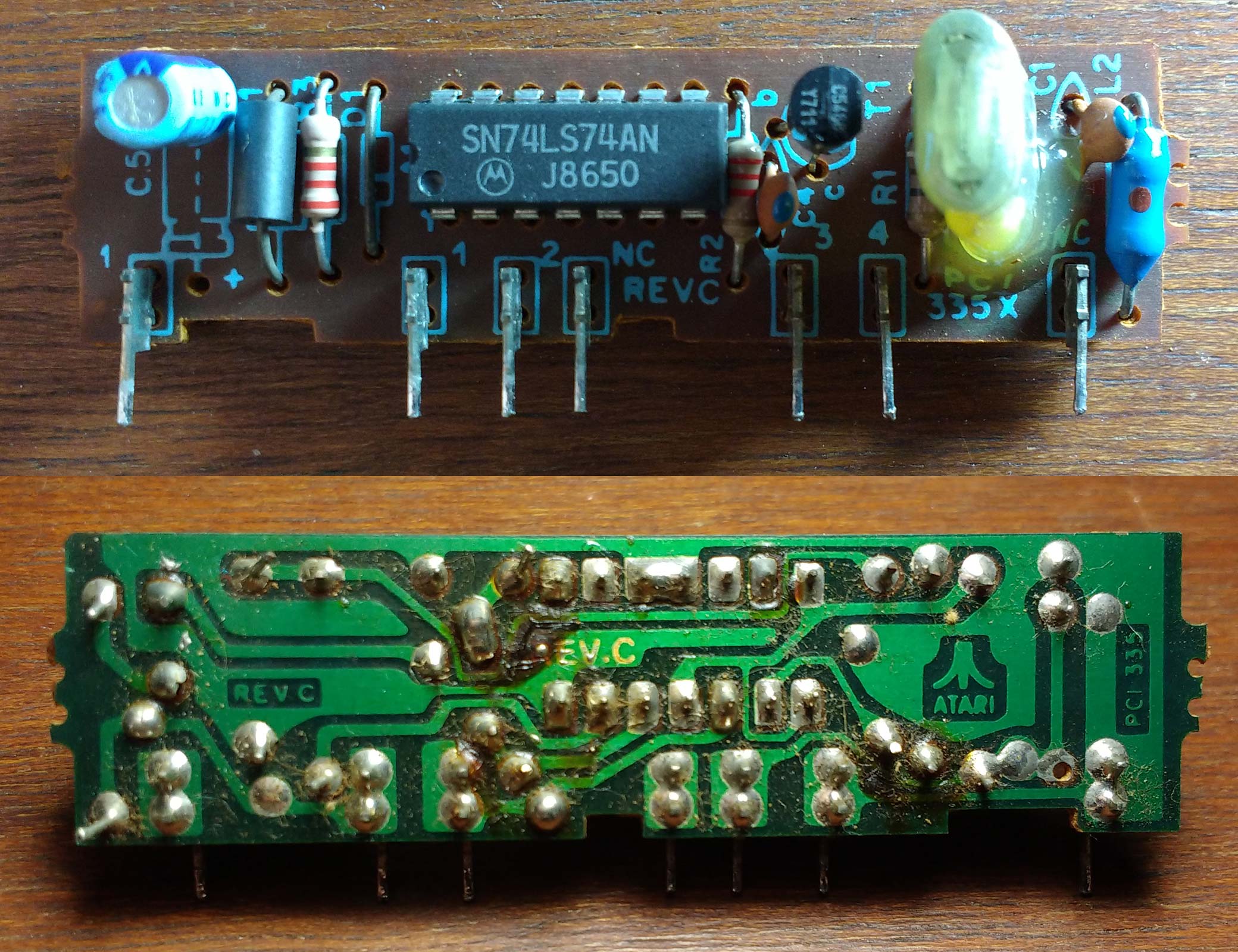
I also could get the scanned Phantom System's schematics, wich I'm sharing here, just in case someone else needs it.
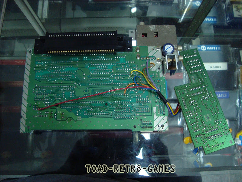
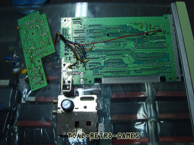
Just if someone is as curious as I am, here's the Playtronic's NES transcodification board.
A far more complex circuit. I just wish to know how it's plugged on the mainboard and how it's doing it's job...
The solder side:
Attachment:
File comment: Solder side
 Nes BR Transcoder - Solda.png [ 1.78 MiB | Viewed 3759 times ]
The componnent side:
Attachment:
File comment: Component side
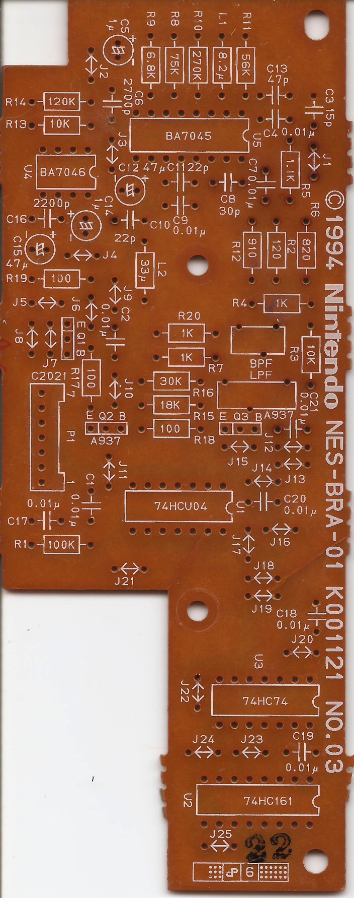 Nes BR Transcoder - Componentes.png [ 1.58 MiB | Viewed 3759 times ]
I know the smaller IC (BA7046) is a sync separator. The other IC (BA7045) is a NTSC to PAL format converter. I just can't understand the TTL chips on it, to sync?
Maybe they didn't made a good job, since I saw many of these NESes with altered colors
I still need to do the Phantom's circuit and see how good (or bad) the image becomes...
I also would like to know how the french NES does RGB.
Probably it has an extra board to split the signals.
Would love to see this extra board!!
The French NES has an internal PAL decoder. But I too wonder about its comb filter or lack thereof. Without one, you get Hanover bars.
I can see why that board was taken out of the system... It cracked. Probably someone fastened the screw too tight and it snapped.
Fisher wrote:
I also would like to know how the French NES does RGB.
The silver box that would have contained the RF modulator instead contains a Sony V7021 = CXA1621, an all-in-one NTSC-or-PAL-to-RGB demodulator.
Its datasheet recommends a 1-scanline delay line (i.e. the comb filter), which would conceal the Hanover bars. We'd need an actual picture of the component side (to match the
occasional good
ones we can get of the solder side) to make sure they're doing that.
As far as the daughterboard you posted pictures of... I'm tracing it now. I'll edit this post, or add a new one, as I figure out more of what's going on.
The 74'161 (and 1/6 of the 74'04) is making a divide-by-3. It'll count 13 14 15 13 14 15 &c. It's clocked by a highpassed version of some signal from P1 (pin2 - C1=10nF - 7404pin9 - 7404pin8)
Half the 74'74 takes that output to make it a divide-by-6. This should convert the 21.5MHz main clock into the desired modulation frequency
P1 pins:
1 - gnd
2 - 21.5MHz clock input
3 - stop and zero chroma phase
4 - delayed ("acknowledged") and latched copy of pin 3 (latched by falling edge of pin 2)
5 - PAL-M video out
6 - NTSC-M video in
7 - +5V
Not clear what why pins 3 and 4 are wanted here.
I've found some pictures.
Attachment:
 DSC07583.jpg [ 170.64 KiB | Viewed 3725 times ]
Attachment:
 DSC07581.jpg [ 184.55 KiB | Viewed 3725 times ]
Attachment:
 DSC07588.jpg [ 172.37 KiB | Viewed 3725 times ]
Attachment:
 Captura de tela de 2017-02-08 10-38-44.png [ 909.79 KiB | Viewed 3725 times ]
Looks like the board pins are these cable colors:
Code:
1- Brown
2- Red
3- Orange
4- Yellow
5- Green
6- Blue
7- Purple
The orange wire should be PPU /INT (or is it PPU /RST?).
I just can't figure out the yellow wire...
Is it GND??
Looks like it has a trace cut near the CIC and it's soldered on it.
@l_oliveira I'm not sure, but I think this board was from a NES that was on a flood.
If I remember correctly, the owner opened it and it was full of the river's water.
This may had damaged the board. Or, as you said was the screw.
The rest of the unit was on a miserable state... very dirty and smelling like sewer.
That was sad!!
My advice is not use that board as it causes wrong colors on RED and GREEN (RED becomes purple-ish and GREEN becomes "brown-ish" due to color matrix differences between PAL and NTSC encoding). If you must use PAL-M, use a native PAL-M PPU from UMC as that will give you correct, perfect colors.
Nintendo would never buy a PPU from a pirate/clone company nor would put money at making a proper PAL-M PPU for the NES, but they did modify the SNES, N64, made the Game Cube and Wii support for PAL-M natively as manufacturing option.
Because they would not buy a clone PPU nor make a new one for Brazil they decided on making that bodge board.
Sure! I saw some of these NESes with color problems.
Some of them got fixed afer a couple of resets, others don't...
Have you seem a transcoded Phantom? How good (or bad) is it?
I agree with you. A proper PAL-M PPU would be the best solution, but I'm kind of going on the cheap side, since most of the parts I already have at hand.
I'll try to take a picture of the Hi Top Game and this Phantom screens for comparisons.
I'm not sure if the PPU's palette are different or the decoding circuit at the TV is confused and gives sort of different colors.
I would say that the colors are "stronger", but not saturated.
Well... I just don't know how to describe it properly, so, some pictures may be better.
Any game suggestions? I was thinking in write a palette test program to a flash ROM (
this one from Blargg seems just fine) and take pictures, but this will take some more time. Maybe I try Ninja Gaiden, Battletoads and Super Mario Bros 3.
Any chance you know what was modified on the Wii?
I just got one with a dead drive but no loaders worked on it...
Looks like the game checks the drive at runtime.
There's a encrypted text file on the system menu "directory" which contains the unit unique serial number, target game region, video system settings and model number. Edit that is how you change a Wii from one region to another. (or edit anything else you feel like about the unit)
There are homebrew game loaders which are capable of putting the Wii into PAL-M mode temporarily and there are automated homebrew utilities which can edit the said text file allowing one to make a NTSC or PAL Wii into a Brazil Wii.
1- Brown [gnd] - ground in the pictures, also
2- Red [21.5MHz] - from crystal driver
3- Orange [reset chroma phase] - PPU /IRQ - so the chroma phase will reset on most vsyncs, usually keeping the dot crawl pattern fixed
4- Yellow - ???
5- Green - [PAL-M video out] - they've removed the 510Ω resistor R2, and put this board in place
6- Blue - [NTSC video in] - other side of above resistor
7- Purple - +5V drawn from the modulator daughterboard
Fisher wrote:
I just can't figure out the yellow wire...
Is it GND??
Looks like it has a trace cut near the CIC and it's soldered on it.
Well, it's an output (from the 74HC74). I have no idea what the main board would do with the information.
Maybe they cut the trace from PPU /INT to CPU /NMI somewhere? and yellow ultimately goes to the CPU /NMI pin?
I think the yellow wire goes to PPU /RST.
Does it makes sense??
Attachment:
 cic_pin9.png [ 246.46 KiB | Viewed 3105 times ]
Looks like the interrupted trace is the one thar leaves pin 9 of the CIC.
If I traced it right, it comes from the CPU reset circuit and the side of the track who gets the yellow wire goes to the PPU, after the cut.
To be sure, only if someone with a Playtronic's NES opens it and confirms.
Or if better pictures are found/taken.
I took some pics with my crappy cellphone.
But the ones that showed a little difference were the SMB3 ones:
Phantom:
Attachment:
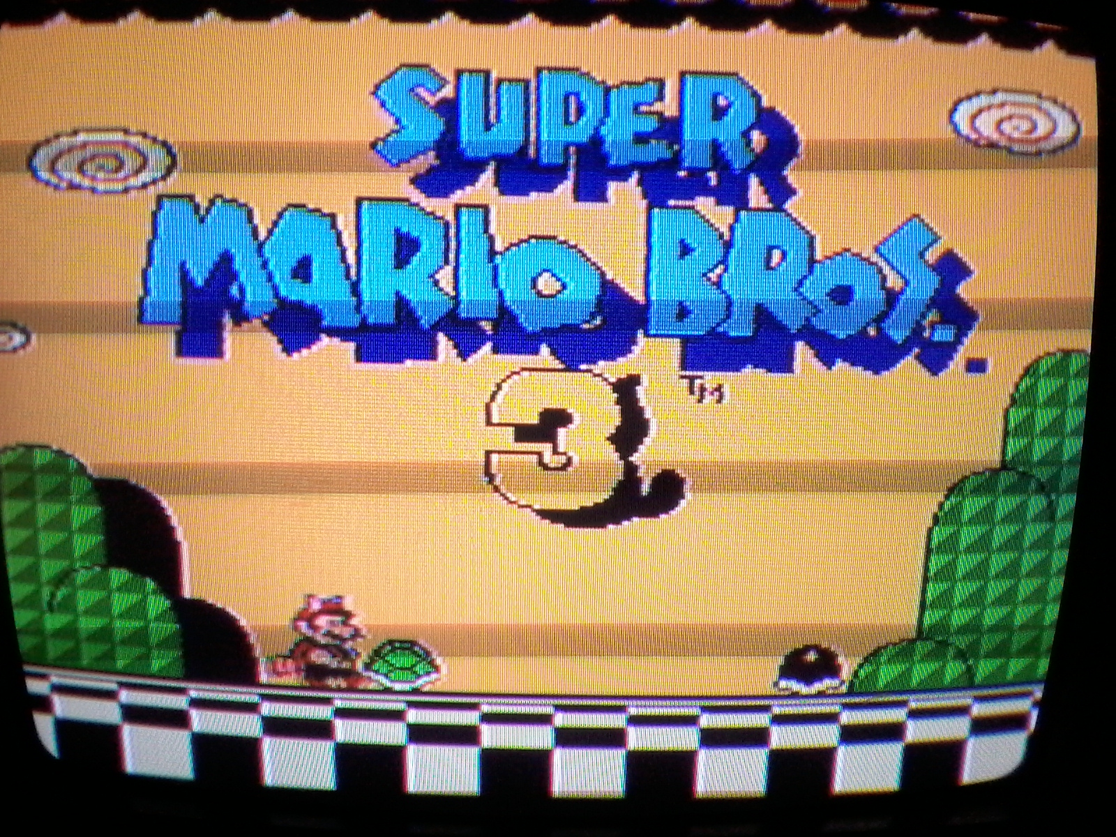 20170208_211949.jpg [ 1.1 MiB | Viewed 3105 times ]
Hi Top Game:
Attachment:
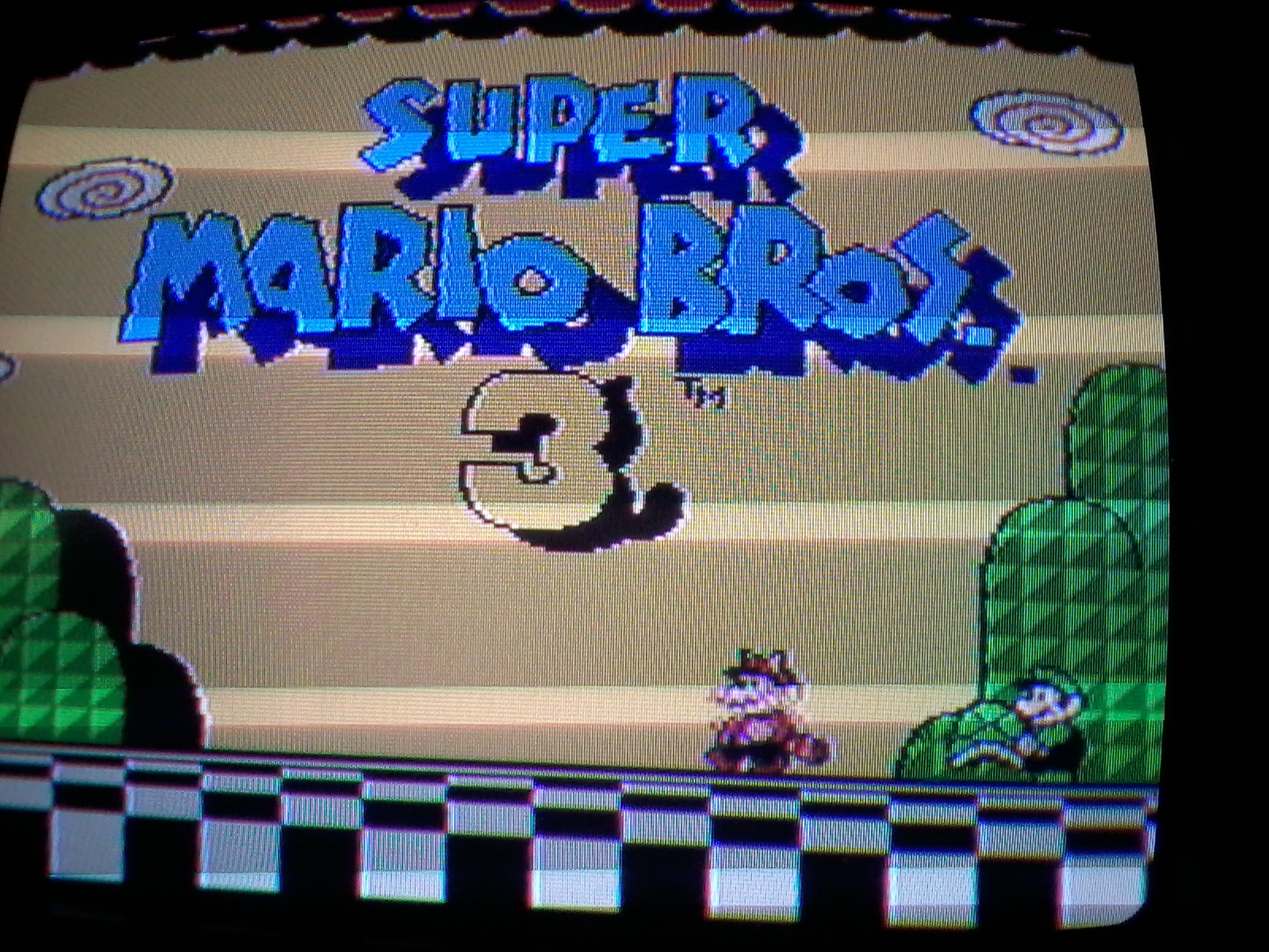 20170208_212319.jpg [ 1002.43 KiB | Viewed 3105 times ]
Does the PPUs have different palettes?
I think not, the color difference may be because of the unfinished transcodification that's somewat confusing the TV's circuits.
The word Ninja in Ninja Gaiden's title seems more red on the Phantom and light pink on Hi Top Game.
The earth on Battletoads seems more brown on Phantom and a little pink on Hi Top Game.
But these didn't appear different at all on the pictures I took.
Wich should be right?
l_oliveira wrote:
There are homebrew game loaders which are capable of putting the Wii into PAL-M mode temporarily
I think I'll try this!!
Any idea about the drive problem?
I saw a drive around for R$100,00 but a complete console (alone, without the cables & etc) for R$150,00...
I also saw a complete Playtronic's NES board (main + transcode) by R$140,00
I really would like to have a "real deal" NES, but unfortunatelly I can't just pay this price
Maybe I can get the "flooded" mainboard from my friend if he still has it...
How hard would be to fix??
I would sure try my luck with the flooded NES... But mostly because I enjoy challenge.
Fisher wrote:
I think the yellow wire goes to PPU /RST.
Does it makes sense??
I don't think so... as far as I know, the PPU shouldn't work for every 1/60th of a second after PPU /RST is low.
Quote:
Any idea about the drive problem?
I saw a drive around for R$100,00 but a complete console (alone, without the cables & etc) for R$150,00...
I think I remember seeing ways to run Wii games off a USB drive. I'm certain you can search for them (rather than having me name names...)
You will unfortunately have to find a functioning Wii to convert existing disks to the USB drive in the first place.
He need a working electronics drive board at least for his wii to be usable anyway.
Oh yeah!
My friend still has the flooded NES.
I gotta try to exchange for something and see what can I do.
Interesting...
If I'm understandig correctly, the Wii sends a command that unlocks the DVD drive before running, sending it a command and waiting for a answer.
Since the drive controller is dead, it don't get this answer.
Maybe I can try to simulate this answer...
But I'm almost sure I will need some kind of microcontroller, wich I don't have access
I know this sure sounds ridiculous, but can it be done with a basic stamp??
Without a working drive, the Wii will boot and stay working for a couple seconds. After a timeout the IOS will flag a fault and send a message to the power pc CPU which makes it switch to a "ouch, I am broken seek service" screen.
Since this thread already got totally out of scope, and I'm on my way to get that flooded NES (and possibly another clone) I think I should create a new one.
The info I got here were great! Thanks!
Maybe I should even ask a thread split when I statted talking about color encoding...
Edit:Just visited the junk pile today and got a UA6548!!
Attachment:
 20170212_113850.jpg [ 588.4 KiB | Viewed 3000 times ]
Attachment:
 20170212_113837.jpg [ 575.26 KiB | Viewed 3000 times ]
With a little work I could fix the pins and now the Phantom is 100% PAL-M.
I think I can use the NTSC PPU to try to fix one of
these boards, if it's really worth the effort...
Oh, and by any chance someone knows what are the missing parts on this board?
Attachment:
 20170212_110208.jpg [ 443.3 KiB | Viewed 3000 times ]
They're marked as C5, R3, R2 and T1.
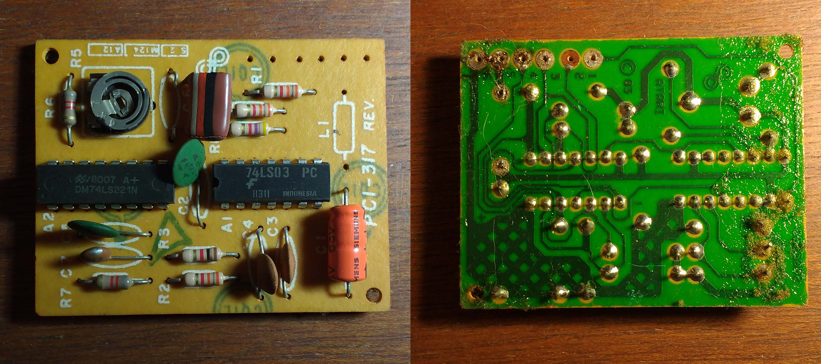
It's a Atari 2600 from Polyvox transcoder board.
Fisher wrote:
Oh, and by any chance someone knows what are the missing parts on this board?
Attachment:
20170212_110208.jpg
They're marked as C5, R3, R2 and T1.
It's a Atari 2600 from Polyvox transcoder board.
There's Polyvox Atari schematics on the internet. If you can't find the schematics and I get any Atari with that board in for repair I can take a picture of the board for you.
Quote:
There's Polyvox Atari schematics on the internet.
The links I found are broken, unfortunatelly
but I found
this pic and looks like both resistors are 2k2, the capacitor looks like a 1mfd. But what about the transistor? It could be a BC558 or BC548?
I also got a Dynavision 3, but seems that I have a sound and power supply/analog board of a different revision.
This page has many schematics for 8 bit systems, but unfortunatelly It hasn't the Polyvox's Atari...
I got no "sign of life" in this clone too...
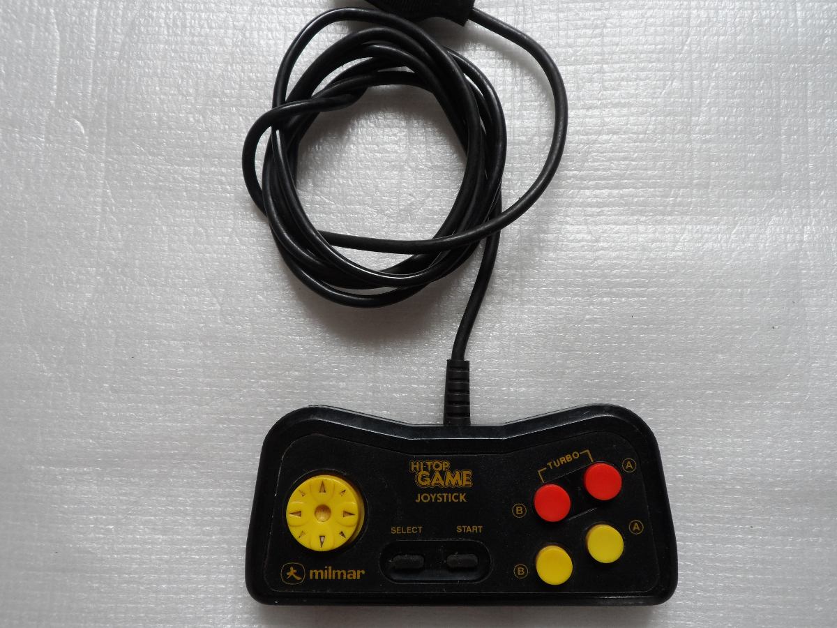
I'm not particularly good with electronics, but maybe I shouldn't jump into the Famiclone fixing bandwagon and fix my Turbo Game controllers. The 2 consoles I own are working fine (one looks terrible though), but the controllers are busted. Can't be hard to fix, right? NES controllers are fairly simple, hopefully these are too. The controller from my other Famiclone (Dynavision) isn't compatible, for some reason.
I really like the Turbo Game because of the dual cartridge slots that will easily work with any cartridge, even Flash carts, reportedly (I never tried because I wouldn't be able to do anything without a controller).
The Turbo Game if I am not mistaken, use the same controller port pinout as the Phantom System so the Phantom System schematics may be of use for you, tokumaru.
The Dynavision, if it's the early kind with Atari like controllers the pinout is likely different and you will need to trace the circuitry.
Phantom System do use the five top pins for standard controller.
l_oliveira wrote:
The Turbo Game if I am not mistaken, use the same controller port pinout as the Phantom System
You're totally right!! In fact, Phantom System, Turbo Game and Hi-Top-Game use the same controllers pinout.
Even the lightguns are interchageable.
As a kid, I used to take my own controller when I was going to play at my neghbor's house, because his 2nd controller was really bad!!
Most problems I saw with controllers are usually the cables or the conductive pads.
Not very difficult to fix though.
I think Dynacom just used a bunch of his Atari clone's cables on his NES clone, but I may be wrong.
My intentions with this thread is to help fix as many clones as possible and also take their schematics and other technical information about them out of obscurity. I remember to have had a Turbogame's schematic diagram on my stuff, but it was before a pipe just broke and "killed" my old comic book collection
.
I never tried to collect the comics again, since read them on the cellphone seems just fine to me. But the schematics may have been "dissolved" with them.
Aww that's some sad story.
I also have things I lost from my childhood but have such good memories from.
Anyway if any more questions pop up I'll try to be of help.
l_oliveira wrote:
Aww that's some sad story.
Unfortunatelly... But it's really fun to read them in english, so I can learn a little bit more
.
l_oliveira wrote:
Anyway if any more questions pop up I'll try to be of help.
That's great, since as most of you may have noticed, my knowledge is not that great.
But with the community helping, I think most of the problems can be solved in the best way possible!!
Fisher wrote:
l_oliveira wrote:
The Turbo Game if I am not mistaken, use the same controller port pinout as the Phantom System
You're totally right!! In fact, Phantom System, Turbo Game and Hi-Top-Game use the same controllers pinout.
The
last time we talked about it, TmEE said there were two different pinouts for famiclone controllers. Do the majority of famiclones use this pinout? I was hoping that if I ever get into Genesis programming, I could somehow autodetect the use of a famiclone controller instead of a 3- or 6-button Genesis controller and support that.
Most famiclones use the 15pin connector used on the Famicom. I believe that it's Brazilian clones that were using the 9 pin connector.
Dynavision wiring is meant to re-purpose Atari joystick cables. So it uses both rows.
Gradiente pinout uses only the five pins on the top.
Finally!!
I searched my stuff and found a Polyvox's Atari schematics.
It doesn't have the PAL-M board though
I scanned it at 300dpi/8bpp and pasted the resulted images.
Hope it's fine. What do you think??
Attachment:
 Esquema Atari Polyvox 300dpi.png [ 3.63 MiB | Viewed 3230 times ]
tepples wrote:
TmEE said there were two different pinouts for famiclone controllers.
I think I saw a DVD game using the same pinout as the Dynavision.
You can check
this link from Luccas homepage and take a look at the Dynavision 3's schematics if you wish.
Maybe should be a good idea to upload these schematics here, just in case something happens with his page...
Fisher wrote:
I searched my stuff and found a Polyvox's Atari schematics.
Nice! I've been meaning to fix a couple of bad Polivox 2600's I have lying around, so this could possibly help me out. There are different Polivox models though... I have an earlier one with a proper 2-sided green PCB and a newer one with a cheaper looking 1-sided brown PCB. I can't tell if there are any significant differences in the circuit though.
Quote:
It doesn't have the PAL-M board though
I'm sure I have one of these boards in here somewhere, which I took off the Atari I successfully converted back to NTSC. Do you want me to take some pictures of it or something?
Great!
I need to be able to identify the capacitor marked as C5 and the transistor T1 (it's the only transistor on this board :-b).
Also, please confirm to me if R2 and R3 are both 2k2.
You don't happen to have a Playtronic's NES laying around that you could use to clarify where the infamous yellow wire connects to, do you?
Thanks in advance.
Here are the pictures. I took them before you asked for these specific parts, so I'll check those now. I just realized I have the board for the other 2600 model too, and the Playtronic NES board, so I took pictures of them as well:
Attachment:
File comment: Polyvox Atari 2600 PAL-M board (1-sided brown PCB model)
 pal-m-polyvox-atari-brown.jpg [ 437.48 KiB | Viewed 3219 times ]
Attachment:
File comment: Polyvox Atari 2600 PAL-M board (2-sided green PCB model)
 pal-m-polyvox-atari-green.jpg [ 423.92 KiB | Viewed 3219 times ]
Attachment:
File comment: Playtronic NES PAL-M board
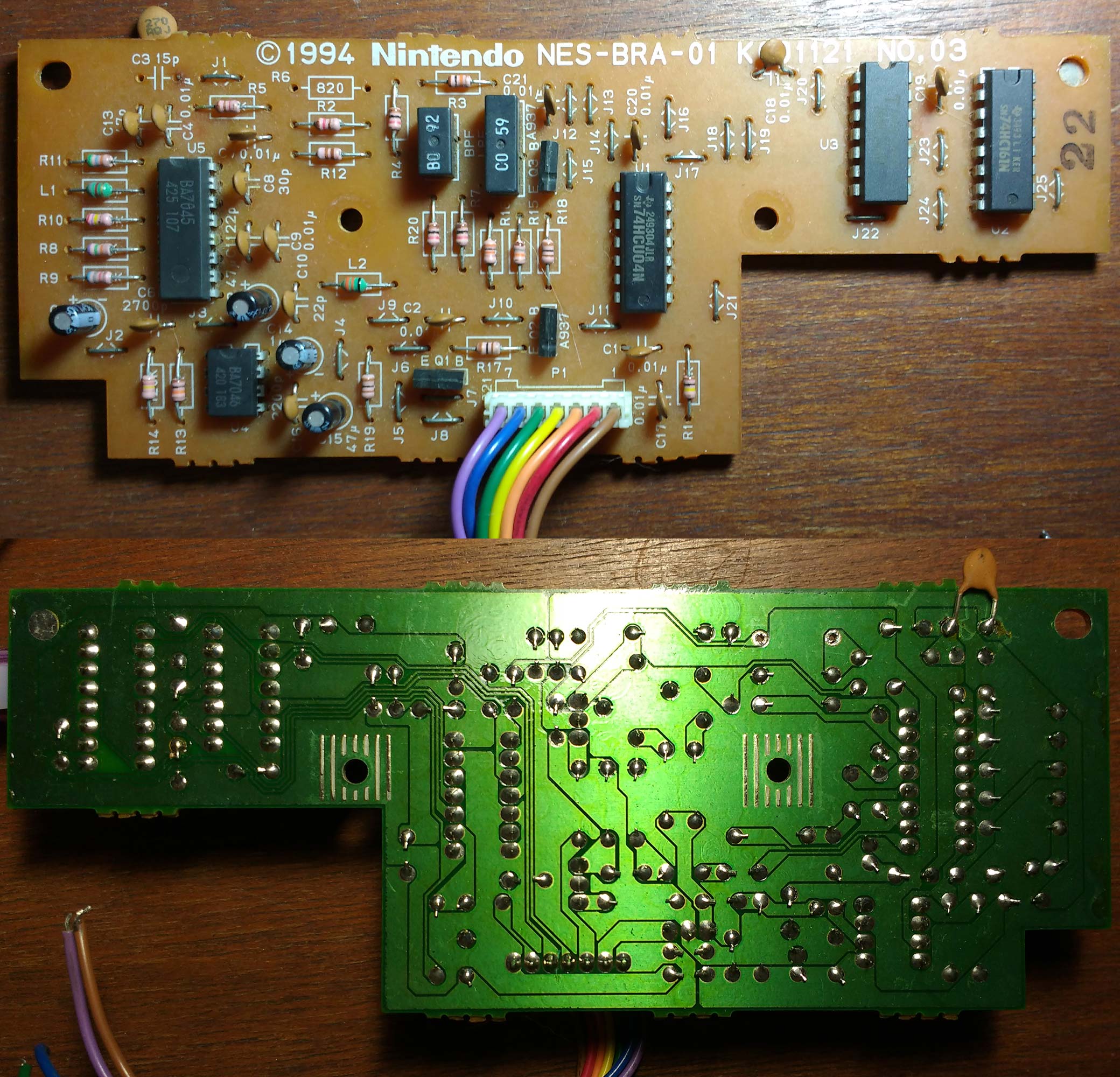 pal-m-playtronic-nes.jpg [ 531.44 KiB | Viewed 3219 times ]
Thanks!!
Unfortunatelly I still can't know the electrolitic value.
I bet it's a 1 Microfarad. (how am I supposed to type the Micro symbol?)
The transistor is a BC548!!
I'll try to reassemble that stuff as soon as I can!!
I still don't know where the yellow wire is connected on the NES' board though.
It's the only piece that is missing in
this puzzle.
Fisher wrote:
Unfortunatelly I still can't know the electrolitic value.
I bet it's a 1 Microfarad. (how am I supposed to type the Micro symbol?)
The transistor is a BC548!!
Here they are:
Attachment:
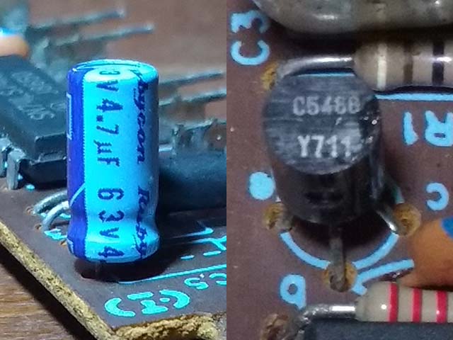 pal-m-polyvox-components.jpg [ 40.96 KiB | Viewed 3216 times ]
Quote:
I still don't know where the yellow wire is connected on the NES' board though.
It's the only piece that is missing in
this puzzle.
This board came from a failed attempt to convert a Playtronic NES to NTSC, which is pretty much dead now (the NTSC crystal I bought didn't work and putting the PAL-M one back didn't do anything, so I'm not sure what to do about that...) and I can't tell where the yellow wire came from (I took pictures back in the day but have no idea where they are now). I do have another Playtronic NES that I could check, I'll try to do it when I find the time to sit down an open it. Can't promise it will be soon though.
If you ever come by Brasilia area let me know I am sure I can revive your nes. I'd wager you broke a trace on the oscillator circuit and it's no longer oscillating. No clock, no video.
Btw, the Polivox Atari with "proper green board" is simple a REV 16 4 switches USA board. It was not made in Brazil hence why they had that transcoder board inside the ICs cage stuck inside with a sponge on the bottom so it would not rattle.

Fisher wrote:
I still don't know where the yellow wire is connected on the NES' board though.
There's really only two possibilities:
1- It's not needed, and so It doesn't actually go anywhere, or
2- The trace from 2C02 /IRQ to 2A03 /NMI is cut and yellow goes to the latter.
I remember undoing a Playtronic NES transcodification once. All I had to do was replace the color crystal, stuff the missing resistor on the video amp and remove the wires for the transcoder board.
http://nesarchive.net/v4/tutorial/retra ... para-ntsc/http://blogonap.blogspot.com.br/2015/05 ... ional.htmlBoth these guides tell you to remove the transcoder board, fix 2 broken traces, and swap the crystal. They don't say anything about a missing resistor.
As for the Atari 2600, this tells you to remove the board, swap the crystal, and *remove* a capacitor and bridge the connections for whatever reason... I didn't do this step and the conversion turned out fine.
http://maniacogameroom.blogspot.com.br/ ... -para.html
tokumaru wrote:
Here they are:
Thanks again!!
More one doubt solved!
lidnariq wrote:
1- It's not needed
I really think this is the answer.
Maybe the orange wire too.
@tepples:
These are the pinouts I'm aware of:
Code:
------------------ ___
/-----------------/ | \
\ o1 o2 o3 o4 o5 / |4o \
\ / |2o o7|
\ o6 o7 o8 o9/ |2o o6|
------------ |1o o5|
-------
Phantom Dynavision Nintendo
1- Gnd Vcc Out
2- R/W R/W Clk
3- Clk Clk R/W
4- Out Out Gnd
5- Vcc Shot Shot
6- Shot Gnd Trig
7- Trig Audio Vcc
8- - Audio -
9- - Trig -
Edit:
@l_oliveira:
Does the TV's image looks better after the modification?
I've done some original NTSC vs original PAL-M comparisons on my old TV.
Unfortunatelly, I've seem no difference...
Maybe it's the TV, since it was a CCE one...
But I think I already said that I think it's a good idea to let the consoles on the original designed state.
You guys make me want to take that picture to solve the mystery of the yellow wire... I can't believe they'd have the wire if it wasn't needed.
Instead of cutting the trace
here, they could instead have removed R2.
(That's my best guess as to the described difference)
In the
other picture I
still have no idea what's going on with the CIC, but this picture clearly shows reconnecting
CIC /RESET OUT to the CPU's and PPU's /reset input.
This makes me even more confused...
Does the yellow wire really connects to PPU /RESET??
As stated before, this makes no sense...
Maybe orange doesn't connect to PPU /IRQ ???? Maybe orange instead connects to CIC /RESET OUT ?
This would ensure that the color modulator booted up in a fixed phase relative to the PPU.
Fuck, does the NES have a lot of screws! Here's where the wires go:
Attachment:
 pal-m-nes-01.jpg [ 780.71 KiB | Viewed 4374 times ]
Attachment:
 pal-m-nes-02.jpg [ 713.94 KiB | Viewed 4374 times ]
Attachment:
 pal-m-nes-03.jpg [ 943.05 KiB | Viewed 4374 times ]
Forgot to take a picture of the other side of the main board... hope you don't need it, 'cause I already put the NES back together!
Anyway, the only cut trace I can see is the one by the yellow wire.
@lidnariq:
Yes, this makes a lot more sense!
It would potentially sync the PPU and the transcoder.
Bad colors could be related to something around these wires, interference maybe? (Likely not, but...)
I'll take a closer look at the pictures I've posted before to try to confirm that.
Maybe Tokumaru can also confirm the orange wire when he looks at it?
@l_oliveira:
Maybe Zepper would like your help too.
Looks like the guy that was fixing his console had not get good news yet.
I have no idea of where he lives...
I don't offer my help because I'm not yet confident enough to try to fix other people's stuff, only my old crap. So if it dies, it's dead (I still didn't understand how the heck I've fried a 9112, an MMC3 clone. Shouldn't it accept a high level on any of his pins, except GND? ).
I think I'm still a very unexperient rookie, with tons of stuff to learn and lots of information to "digest".
Orange appears to be PPU /RST... and yellow to the CIC... Is this correct?
Ok, somehow I got orange and yellow backwards. How did I do that?
Yellow is CIC /RESET OUT, and orange is the buffered and synchronized copy of it that's forwarded to the mainboard for CPU /RESET and PPU /RESET.
Does that make the work of the transcoder board any easier to understand?
Great!
More one mistery solved!
Thanks again!
So these 2 wires are used to sync the PPU and the transcoder, just as Lidnariq said!
What could cause the bad colors?
Something related to these signals?
Edit:
Again I was trying to type on the cell phone and got a answer just before posting...
@lidnariq: I think that was my mistake... oops
@tokumaru: yes, it makes sense now!
Probably the transcoder board needs to control reset so it knows when reset is being held low so it doesn't run without video signal coming from the PPU. That would result on weird wavy patterns showing on the screen, I believe.
I believe that bad colors are due to different color encoding used on PAL(YUV) vs NTSC(YIQ). They convert the phase but the signal is still in YIQ as originally generated by the PPU.
YUV and YIQ are essentially the same color space, just with the chroma plane rotated by 33 degrees. Use of YIQ with NTSC theoretically allows for more luma detail without color fringing because the Q axis is narrower in bandwidth, but few TVs support it, most instead decoding NTSC as YUV.
The PPU's output isn't generated with the ordinary QAM (quadrature amplitude modulation) method associated with YUV or YIQ. It's actually 12PSK (phase shift keying) as a shortcut for generating a signal that a YUV or YIQ decoder can still handle.
Oops, missed this post.
l_oliveira wrote:
If you ever come by Brasilia area let me know I am sure I can revive your nes. I'd wager you broke a trace on the oscillator circuit and it's no longer oscillating. No clock, no video.
Thanks. The original crystal had something like a wire around it, soldered to its metal body... I have no idea what the hell that was. One day I'll look into fixing that NES, thanks again for offering to help.
Quote:
Btw, the Polivox Atari with "proper green board" is simple a REV 16 4 switches USA board. It was not made in Brazil hence why they had that transcoder board inside the ICs cage stuck inside with a sponge on the bottom so it would not rattle.
Yeah, it was glued to the top of the CPU and TIA, I think. Very sticky, there's still a bunch of sponge pieces on that board I photographed, and on the chips.
The sponge foam degrades with time. Becomes a pulp after some 20 years or so. The REV16 board is from 1981 and they were sold here around 1984 so they likely had the boards installed in 1983. Plenty of time for the foam to degrade and turn into a sticky, yucky pulp.
Great!!
I'll try to use the carnival's holyday to rebuild/fix the board an do some tests.
I just love this holyday!!
I spend most of the time sleeping and playing with my kids and stuff!!

Hi all,
So if I am to convert my original Phantom System from PAL-M to NTSC all I have to do is to put a NTSC NES crystal in it, nothing more?
Thanks,
Victor
You will need a NTSC PPU too, or else you'll get color only on some TVs, if any.
You need a NTSC crystal and a NTSC PPU IC.
Maybe the transcoding circuit built arount the 74LS74 could be modified to create a correct NTSC color subcarrier from a PAL-M PPU IC?
But the easier way definetelly is to change the PPU.
Can someone suggest a good place to get one NTSC PPU?
I couldn't find one, be it original or clone (the only NTSC clone I know is the UA6528), at least here in Brazil.
I really need to revisit this and the MegaDrive stuff, doing some tests with them.
An interesting fact on the MegaDrive's circuit is that the rainbow banding practically disappears if I use a crystal to generate the Color Subcarrier frequency.
It's becomes very visible if I connect the VDP's output to the encoder.
I really need to draw these schematics and get some pictures...
It will certanly help to show what I mean clearer.
You're transforming the banding into dot crawl by using a crystal for color carrier frequency. The banding is fixed because it's generated by the same clock as the video (the color carrier coming from the VDP is synchronous to the horizontal sync). By switching to a free-running oscillator you have the interference drift around the screen, usually from left to right (may vary depending on the adjustment of the circuit, if there's any or the ambient temperature).
The NES has some measures on the PPU to diminish the effect of the banding/dot crawl artifacts. SEGA stuff not.
Guys, thanks for the quick answers.
Luckily I have spare PPU(RP2C02G-0) here. Hopefully it is working.
I am planning to install the hidef nes mod in the Phantom. I already have the console and the mod kit. Just waiting for the desoldering gun to arrive so I can start the project.
Should I create a new thread or just post here?
Gonna need your help!!!
Fisher wrote:
Can someone suggest a good place to get one NTSC PPU?
I have two NTSC PPU's here but since they are not tested I can't be sure both are working. In case they are I will have one for you.
l_oliveira wrote:
You're transforming the banding into dot crawl by using a crystal for color carrier frequency.
I think you're right, here are some pictures:
With Crystal:
Attachment:
File comment: Carrier with crystal
 my_photo-1.jpg [ 155.59 KiB | Viewed 3819 times ]
With the VDP:
Attachment:
File comment: Carrier with VDP
 my_photo-4.jpg [ 141.83 KiB | Viewed 3819 times ]
Would an S-Video mod eliminate the dot crawl?
The MegaDrive I'm using is a clone, it has jumpers to set many features, but unfortunately it hasn't an US/JP jumper.
I added a switch to do that, but looking at it today I see I totally goofed up back in the day
.
It was being used without a top cover, wich I only could get several months later.
This is the MegaDrive in question:
Attachment:
File comment: MegaDrive Clone
 20170507_102938.jpg [ 860.37 KiB | Viewed 3819 times ]
I found a
switchless mod sometime ago and I'm willin to build it.
Any idea if it works fine?
melovictor wrote:
Should I create a new thread or just post here?
I think it's up to you to decide what is better, both options are fine, I think.
Anyway I really wish to see how this mod will be made.
So please, post as many pictures and videos as possible.
melovictor wrote:
In case they are I will have one for you.
Having an original CPU/PPU set would certanly help in
this project I started a while ago but it is just stuck right now
.
But I'm worried about the costs, specially the shipping.
Fisher wrote:
Would an S-Video mod eliminate the dot crawl?
No, but it will reduce the banding considerably if you return to using the VDP clock. The dot crawl is still noticeable even on S-Video, particularly because it has motion, while the banding is static.
The motion can be distracting for some people. That is the main reason why it's preferable to keep the banding than "upgrade" to dot. crawl...
To get rid of dot crawl AES NEO-GEO have a complex circuitry with a PLL feeding back clock fluctuations from the 3.57Mhz oscillator at the CXA1145 IC into the 24MHz oscillator which clocks the system. Any fluctuations on the color carrier frequency are compensated on the main VDC (Video Display Controller) making sure the clock which generates the horizontal sync keeps in phase with the chroma carrier.
Playstation (the first one) in addition to keep it's chroma carrier in phase with the horizontal, feeds a triangular wave to it's CXA1645 instead of a square wave, further reducing image artifacts on spots where colors change abruptly.
HiDef board in place...
Attachment:
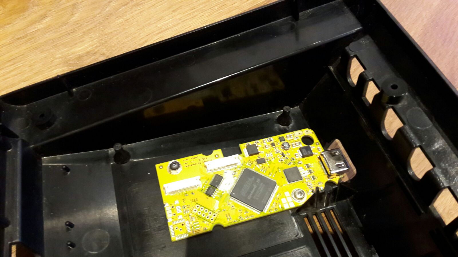 IMG-20170507-WA0115.jpg [ 162.7 KiB | Viewed 3795 times ]
HDMI connector
Attachment:
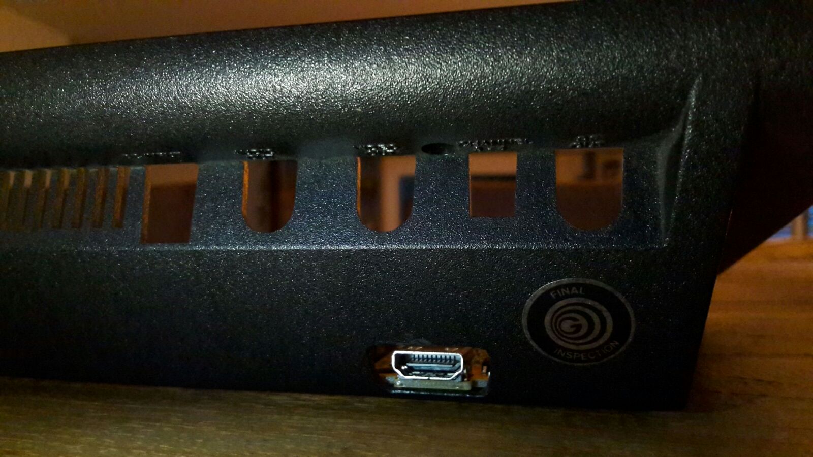 IMG-20170507-WA0109.jpg [ 202.3 KiB | Viewed 3795 times ]
Ok, since it's the same clone I'm having trouble with I think it's a good Idea to ressurect this thread.
What happens is this:
I tried to do a repro, converting an SLROM to SGROM
here.The game I made (a retranslation of Rockman 2) ramdomly reseted / crashed.
At first I tought it was some problem in the repro, but I tried it on two other clones and it worked perfectly.
I tried some other games I have and find that oddly Gradius starts on the gray
"Konami one Gradius ten" (wich means my CHR ROM is hacked) screen.
AFAIK, this screen is invoked by a combination of keys on the joystick.
It seems to stay sending some joystick commands to the console, because the title screen after being iddle for a while instead of showing a small demo gives a quick beep and comes back.
Both joysticks were disconnected when I did these tests.
I tried removing both joystick buffers (74'368) but I got the same results.
I disconected /OE2 and /OE1 from the CPU, same results.
I also changed it's CPU by other from a clone and again, got the same results.
Looks like it's some random component or even the PCB.
What else I can do to troubleshoot this? I'm out of ideas!
In case someonte wants it's schematics to take a look, they can be found
here.
Well, nothing new for now...
I'm trying to disassemble, clean the board, check components an tracks and them will assemble again.
This is what I've got for now:
Attachment:
 IMG_2238.JPG [ 1.73 MiB | Viewed 3159 times ]
Attachment:
 IMG_2239.JPG [ 1.52 MiB | Viewed 3159 times ]
In this clean I've given a eviction notice for a very small spider and other insects that seemed to live under the ICs.

I think that was kind of expected from a thing that was not cleaned thoroughly for at least 20 years.
Interestingly, most of the resistors were like this:
Attachment:
 IMG_2240.JPG [ 1.01 MiB | Viewed 3159 times ]
Looks like they weren't properly placed on the board...
Maybe
this test program by Tepples can help to figure out what / where to look.
I'll take my time to at least put the 74'139 back and the resistor (R4) + capacitor (C2) that plugs the clock generator on the CPU.
Interestingly it booted withouth these components (the resistor and the capacitor, not the IC).

Will the program work fine on a UNROM board?
Thanks in advance.
Fisher wrote:
Maybe
this test program by Tepples can help to figure out what / where to look.
[...]
Will the program work fine on a UNROM board?
Given its structure (CHR RAM based, only $C000-$FFFF used), I'm about 90 percent sure it will. You could try changing the mapper number in its header to 2 (UNROM) to see if it works in an emulator.
Great!
I did as you said and tested on an emulator.
Worked like a charm! Thank you for the tip!!
I'm thinking in put sockets on all of this clone's ICs, would this be a good idea?
I'll try to reassemble at least the enough for it to boot tomorrow.
I'll try post new stuff as they're happening.
Just in case someone else is viewing this and is "cheering" for me.
I don't know if it's visible in the pictures, but there's a lot of opaque stuff that gives this board a kind of "dirty" visual.
I removed a decent amount of it, but to fully remove it i think the only way is to take all the parts out, clean and them reassemble.
Would this be worth the effort?
I mean, it lasted more than 20 years, and a good amount of this time it was on a (very) less than ideal storage.
I know this sounds kind of a "generical retoric sentimental" question, but would this fix make this clone resist for about more 30 years (or even more) or it's really not necessary (would this be just a cosmetic fix)?
I really would love to show the stuff I'm fixing / building / transforming now to my grandsons in the future...
The experience of showing my kids the games and toys I used to play when I was at their age is being great!!
And they're enjoying each new cartridge I build, fix or mod.
It's some opaque 3M tape. They would put it on the board so during wave soldering assembly, solder would not climb through the component leads. They put it mostly at the points where ICs and sockets are soldered to. I suppose that helps out when you need to remove them from the board.
Finally could flash the rom and test.
And the results: No joystick connected!!
Damm!! I just don't know what can be causing this bug and I'm out of ideas again!!
Any suggestion are welcome!!
l_oliveira wrote:
opaque 3M tape
I saw some of these on the component side, but what I'm referring is a thing that seems like dust, is kind of white and opaque and appears on both sides.
The picture just don't do justice showing this thing, I'll try to take a better one tomorrow.
Phantom System has some silly crap on it's design like some control lines of the CPU connected to the cart slot which aren't supposed to...
Audio and Video on the cart slot? Only to make the signals gather interference from the bus signals, right?
Why a cartridge would need/want INP0/INP1 pins or OUT0? (OUT0 may cause interference on the controller ports).
I suggest you cut these traces so they no longer go through the cart slot.
Had OUT0..OUT2 been connected to the cart slot, it could have made small discrete logic mappers cheaper (obviating 3/4 of a 74'161)
Of course, that supposes the existence of developers that can write or port software to use that interface instead.
I cutted /INP0, /INP1 OUT0 and Video out from the cart connector.
I didn't cutted audio because maybe I can do an adapter to FC carts + audio.
Got the same results!!

Fortunatelly, after puting sockets on the 74'139 and in the buffers and put them back in, I ran Tepple's program and got this:
Attachment:
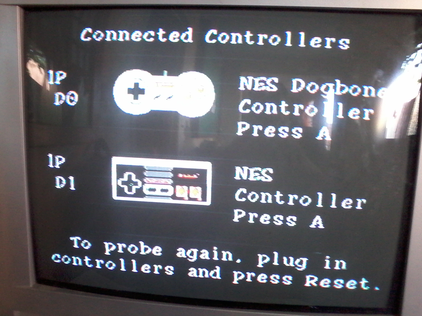 20171020_183115.jpg [ 603.84 KiB | Viewed 2963 times ]
This should be normal, but only the 1st controller was connected.
The controller is like this one:
Internally it's only a epoxy blob.
I also got the Low-level probing results:
Attachment:
File comment: Low-level probing results
 20171020_183059.jpg [ 977.29 KiB | Viewed 2963 times ]
Hope this helps to find some clues on how this can possibly be fixed.
Again, thanks in advance.
...00.SS means bits 4 and 3 are driven to zero, bit 2 is not connected, and bits 1 and 0 are both serial. Based on which bits are driven to zero vs. not connected, it thinks you have a top-loading NES. (It isn't built to recognize famiclones.) And if you have a top-loading NES, it assumes the controllers in ports 1 and 2 are dogbone controllers.
"1P D1" refers to player 3's controller in the Famicom DA15 expansion port, which normally doesn't exist on a top-loading NES unless it's hacked in.
I unplugged Out1 and Out2.
Tested with Gradius and got the same results.
Could this be some problem with the CPU's RAM or the clock generator?
That and the PPU (PPU + latch + RAM) are the only parts I haven't messed around yet.
Why not connecting logic analyzer to CLK/STRB/DATA to see what happens?
I meet tons of broken 74368 but never working CPU with STROBE failure.
Unfortunatelly I don't have one...
Maybe I can build it??
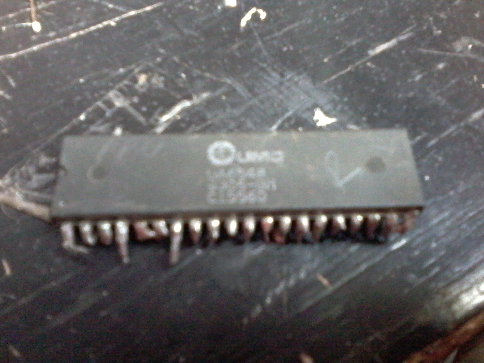
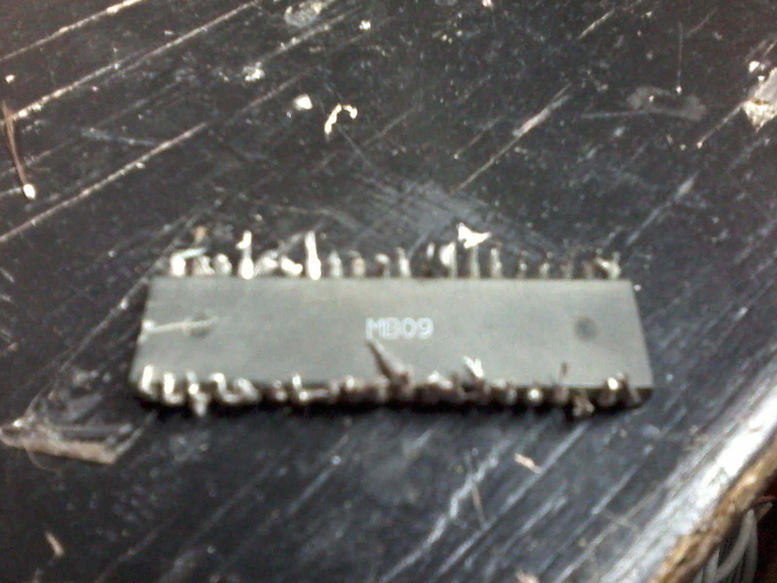
I tried to substitute it's CPU with another from a working clone and got the same results.
That's really bizarre!!
Maybe it's some resistor or capacitor going bad?
Again, I have no idea of what to try next.
Interestingly, I played Rockman 3 on this clone for hours, and some other games like Super C, SMB3 and SCAT too.
Maybe the clone just doesn't "like" Rockman 2 and Gradius.
And I tought machines had no feelings...
OUT1 and OUT2
shouldn't be relevant.
You can get a cheap logic analyzer by getting one of
these and some test clips.
That seems very nice!! I'm putting in my wanted list!!
After getting a logic analyser I should search for what?
I already did tests without both the 74'368 and the resistors and got the same results.
Again, this is bizarre!!
You should be testing for broken traces maybe.
Also have you tested a different CPU IC on that system?
Yes. I tried other CPU and got the same results.
I tested all traces before putting back the demux and the buffers.
Now I'm using sockets on them.
I also checked the TST pin (on the schematic it's marked as /RDY) and it's OK.
What else should I look for?
Maybe an exorcist? lol!
I did a memory test with NES test rom (or whatever name it is).
Altough I didn't see properly the graphics (I only have an UNROM testboard) the sound it made is quite similar to what I hear on an emulator.
With this in mind I'm assuming this test went fine.
Another interesting thing I noted is that it becomes worse if I try using the GameGenie with it.
Rockman 2 reboots as soon as the screen fades after the helmet appears on Rock's head.
With Gradius I got the same results and without the Genie: I just can't start the game at all.
This is what the Rockman's repro looks like on the
component side and the
solder side.
Just in case someome wants to take a look.
The only thing I removed was the resistor, since it seemed to be redundant.
Could a small alteration on the clock generator result on this?
I've tested with a few more games: Battletoads, Q*Bert, Gyruss, Kings of the Beach, Fester's Quest Journey to Silius, Metroid, Bionic Commando, Life Force and Gradius 2. All played just fine. If someone suggests a specific game to test, I'll try to get the game make it.
It would be nice if I could get anoher Gradius and Rockman2 to test, but unfortunatelly I couldn't find anyone around who had it.
I'll post again if I have any other news.
I think I'm probably missing some detail on this weird defect...
For now I'm out of ideas again. Any suggestions are welcome!
Can you make photos of entire PCB of this console from both sides?
Are the resistors pulling up CK/D0/NMI/IRQ etc discrete ones or common resistor ladder?
I had one time funny problem with internal short-circuit in such ladder.
The resistors are all common ones.
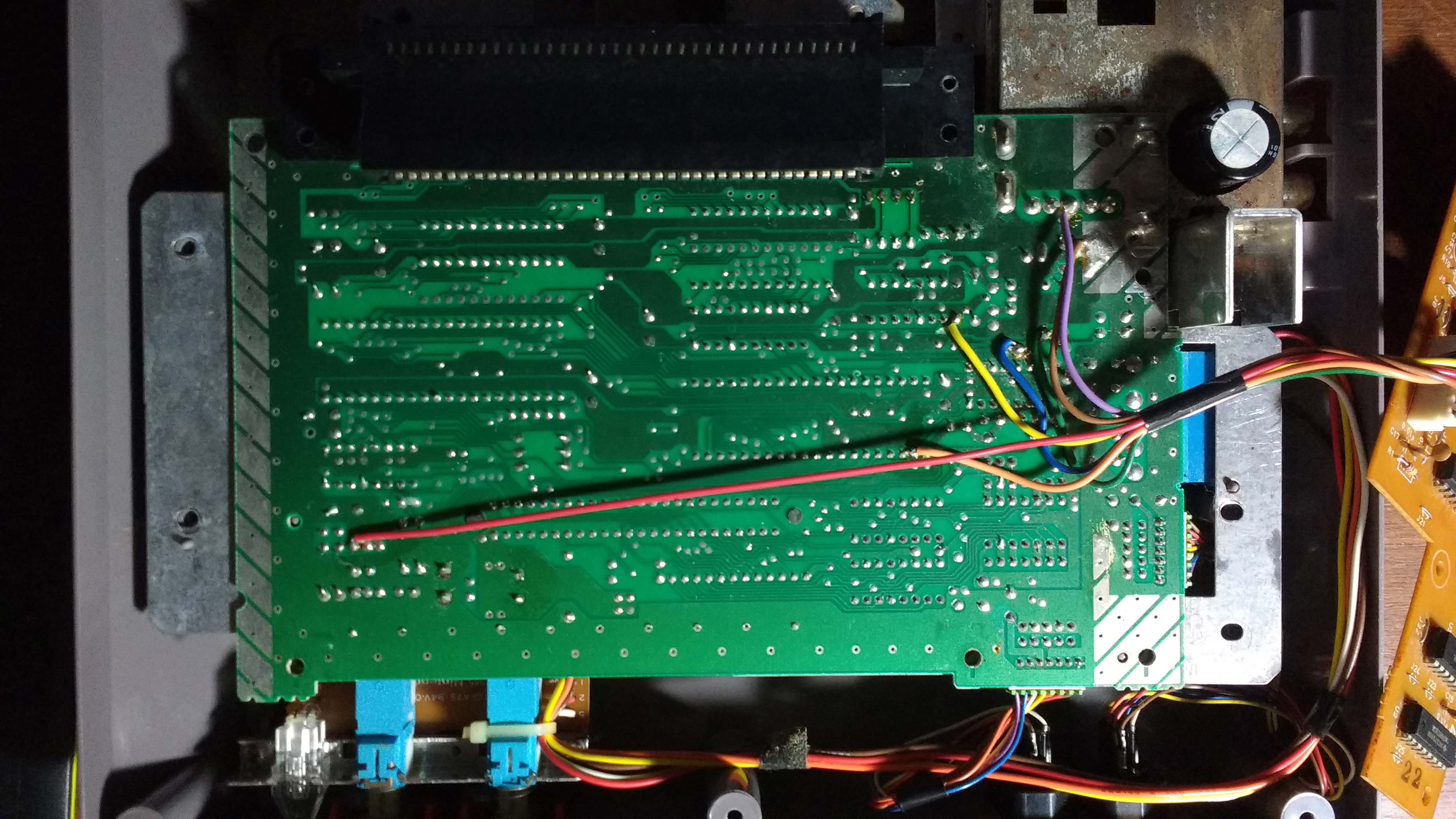
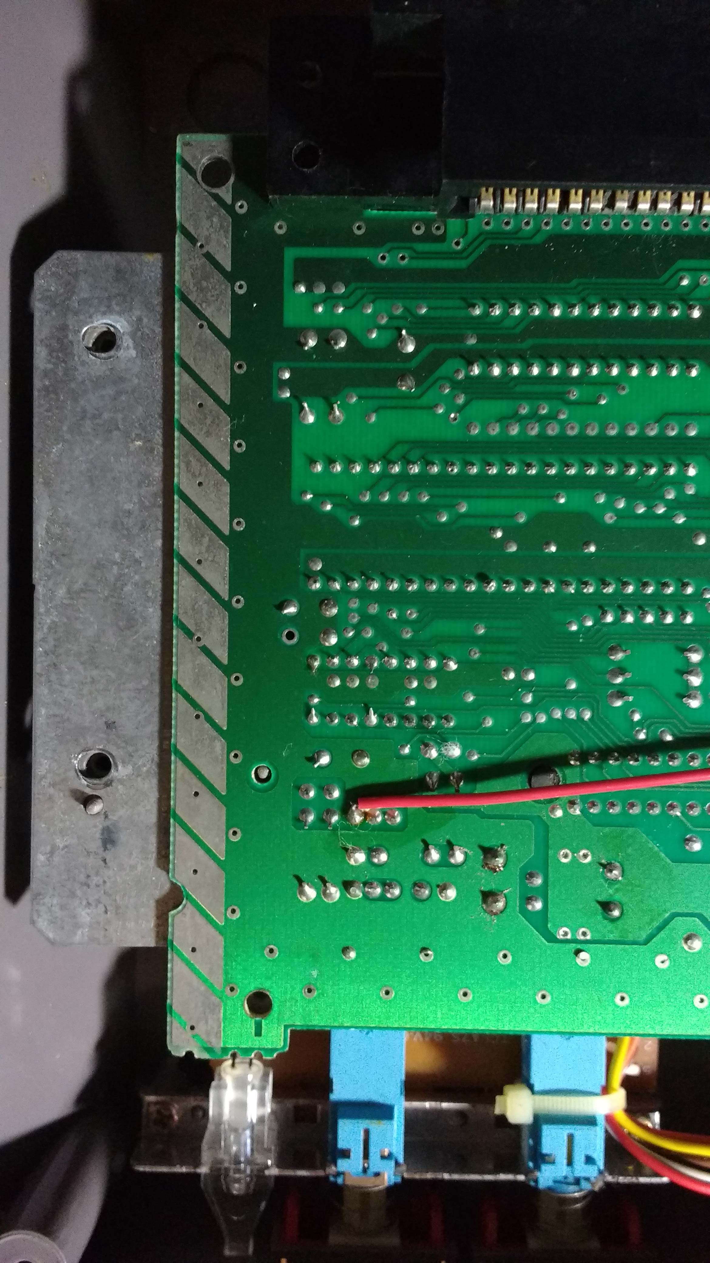
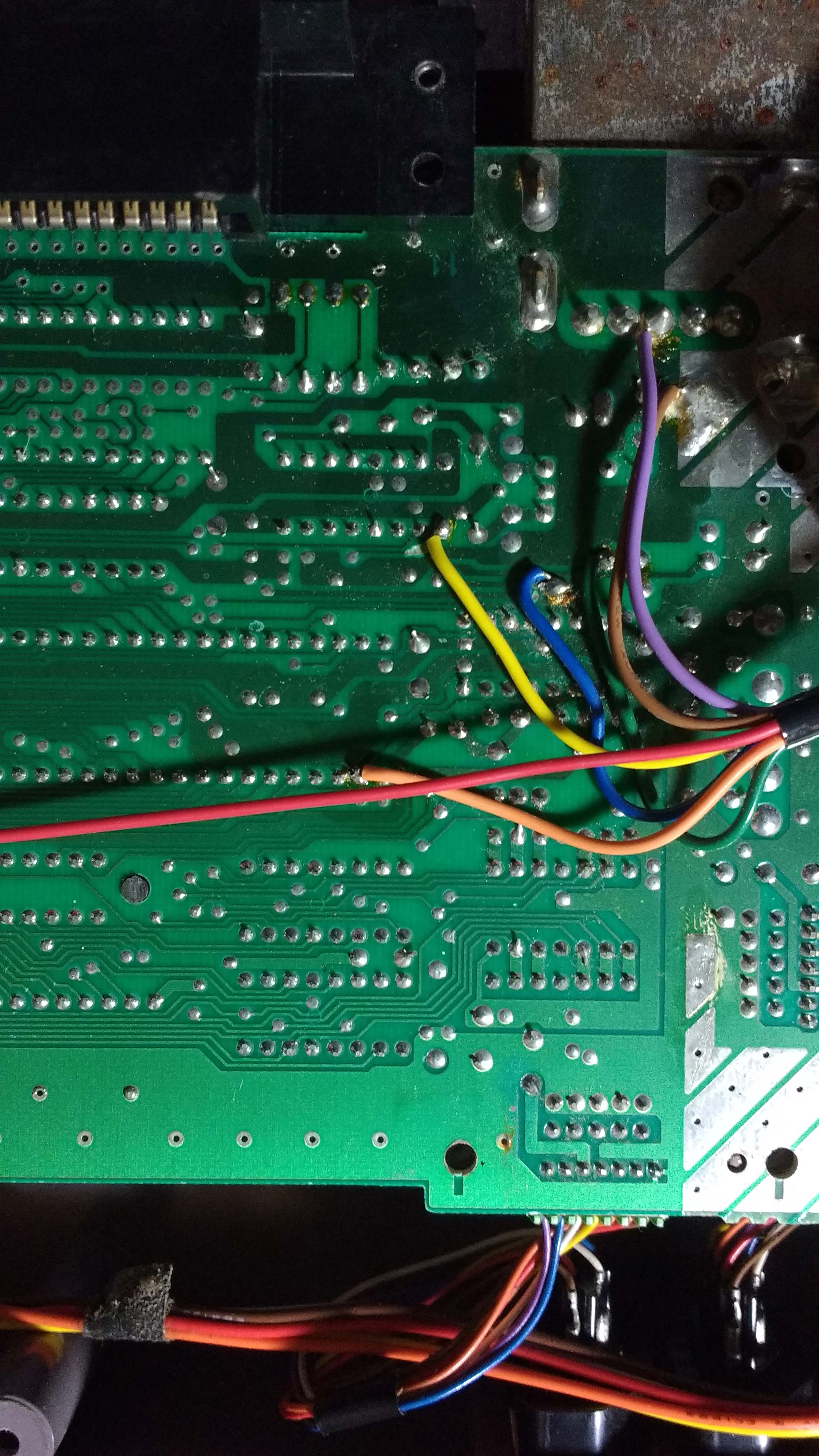
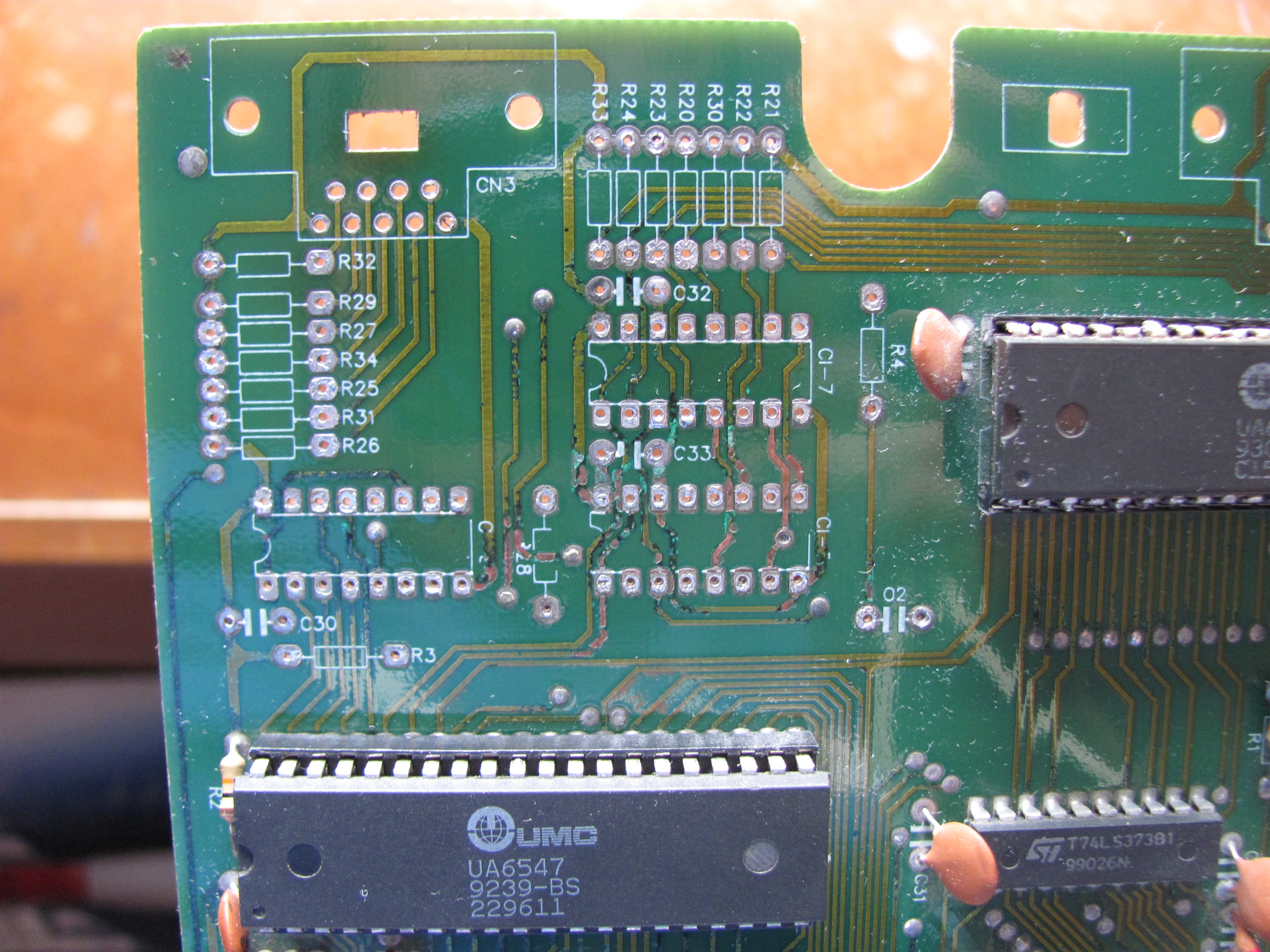
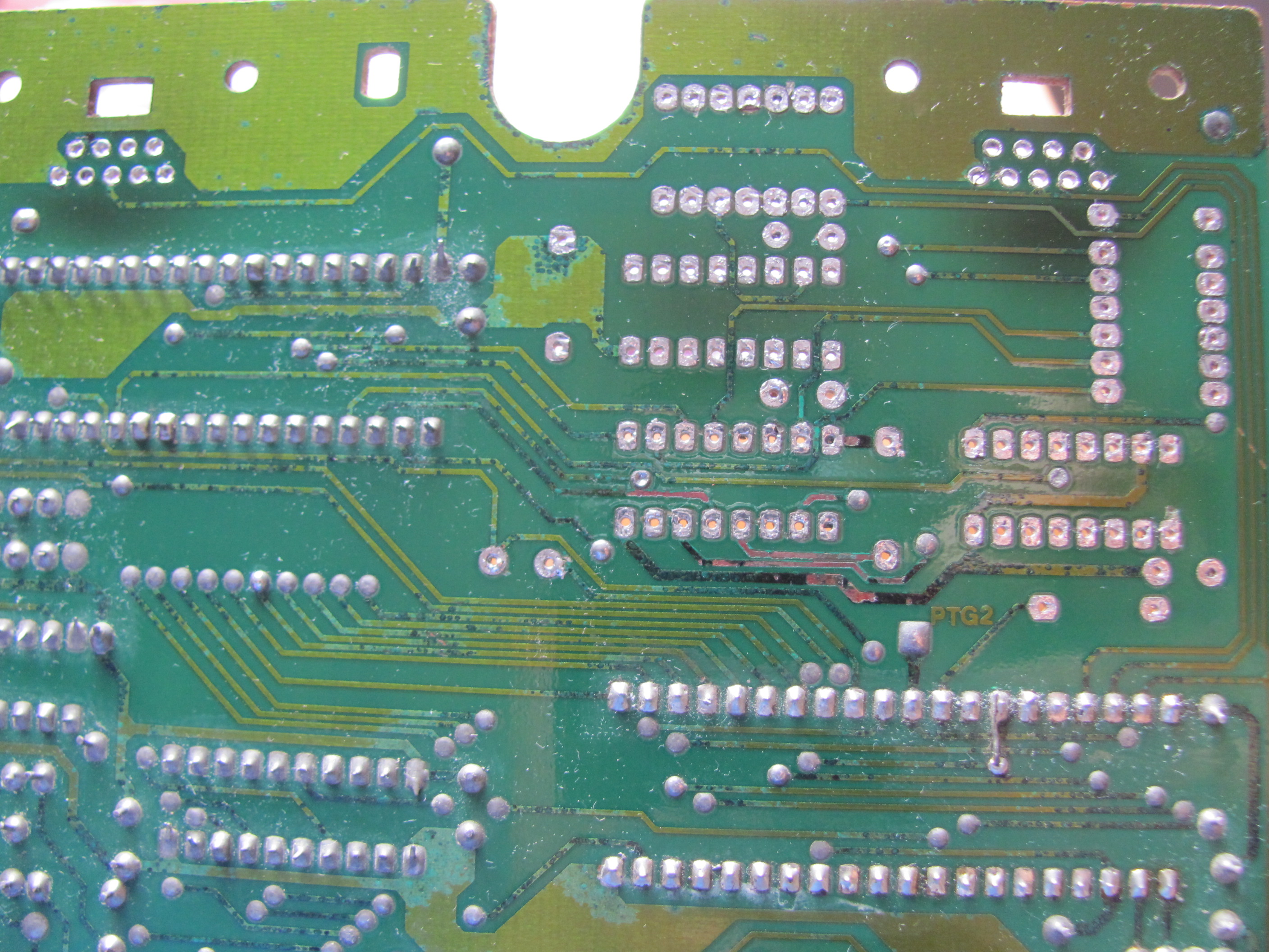
Here are some photos of the mainboard.
I didn't put the 2nd player's buffer back yet.
Hope this helps.
Attachment:
File comment: Component side
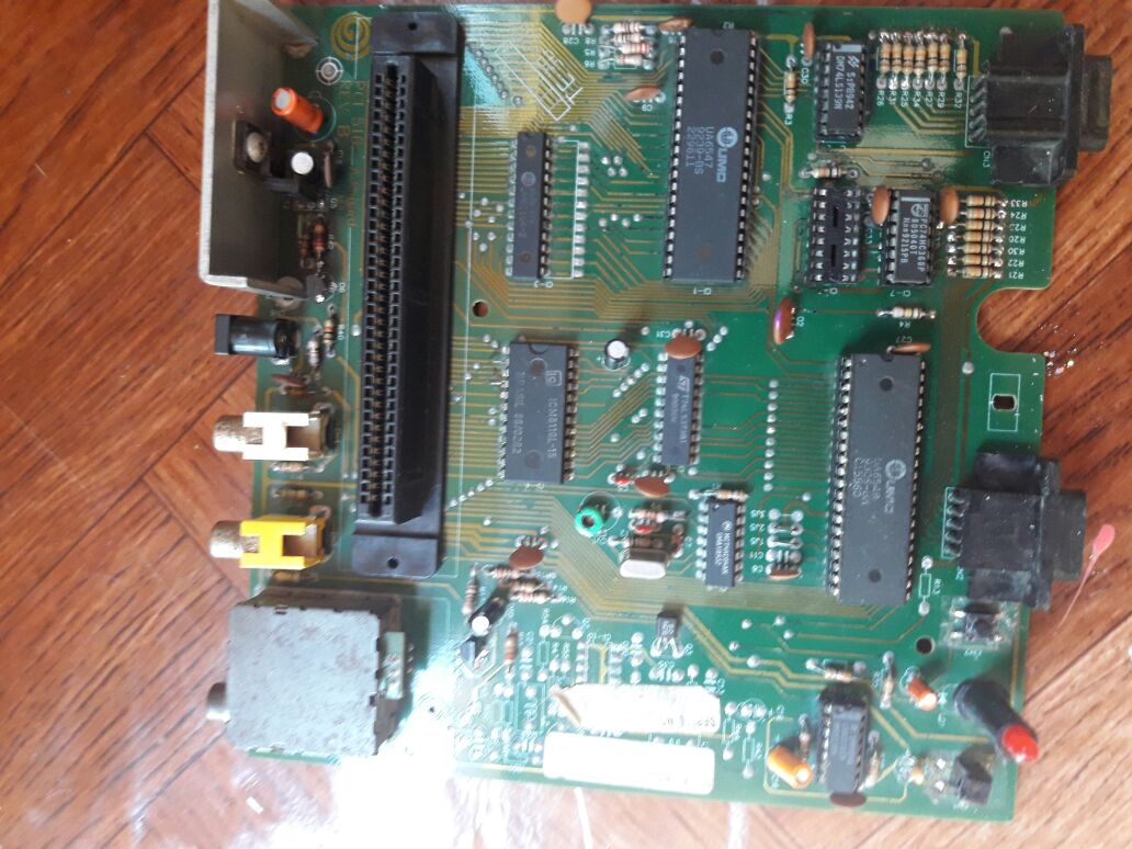 IMG-20171024-WA0002.jpg [ 142.51 KiB | Viewed 2712 times ]
Attachment:
File comment: Solder side
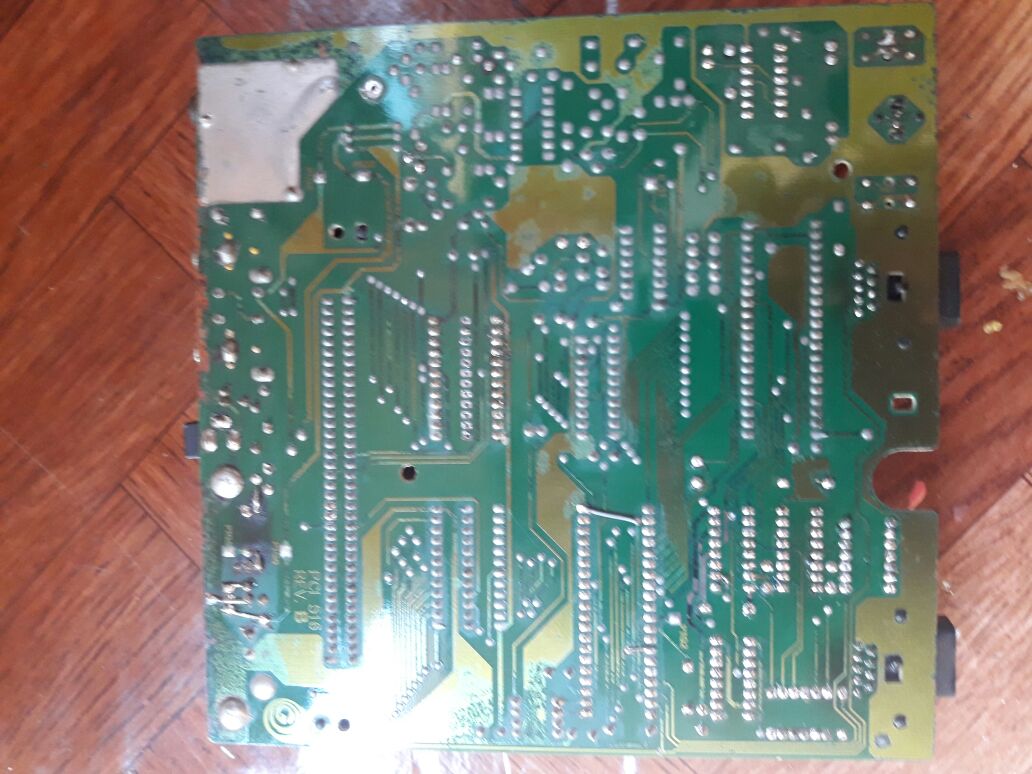 IMG-20171024-WA0001.jpg [ 123.21 KiB | Viewed 2712 times ]
Got some news, not that good, but soo...
I almost think the problem was solved!
I got an old 60 to 72 pin adapter board and the game ran more stable.
It didn't crashed anymore, but it resets a lot.
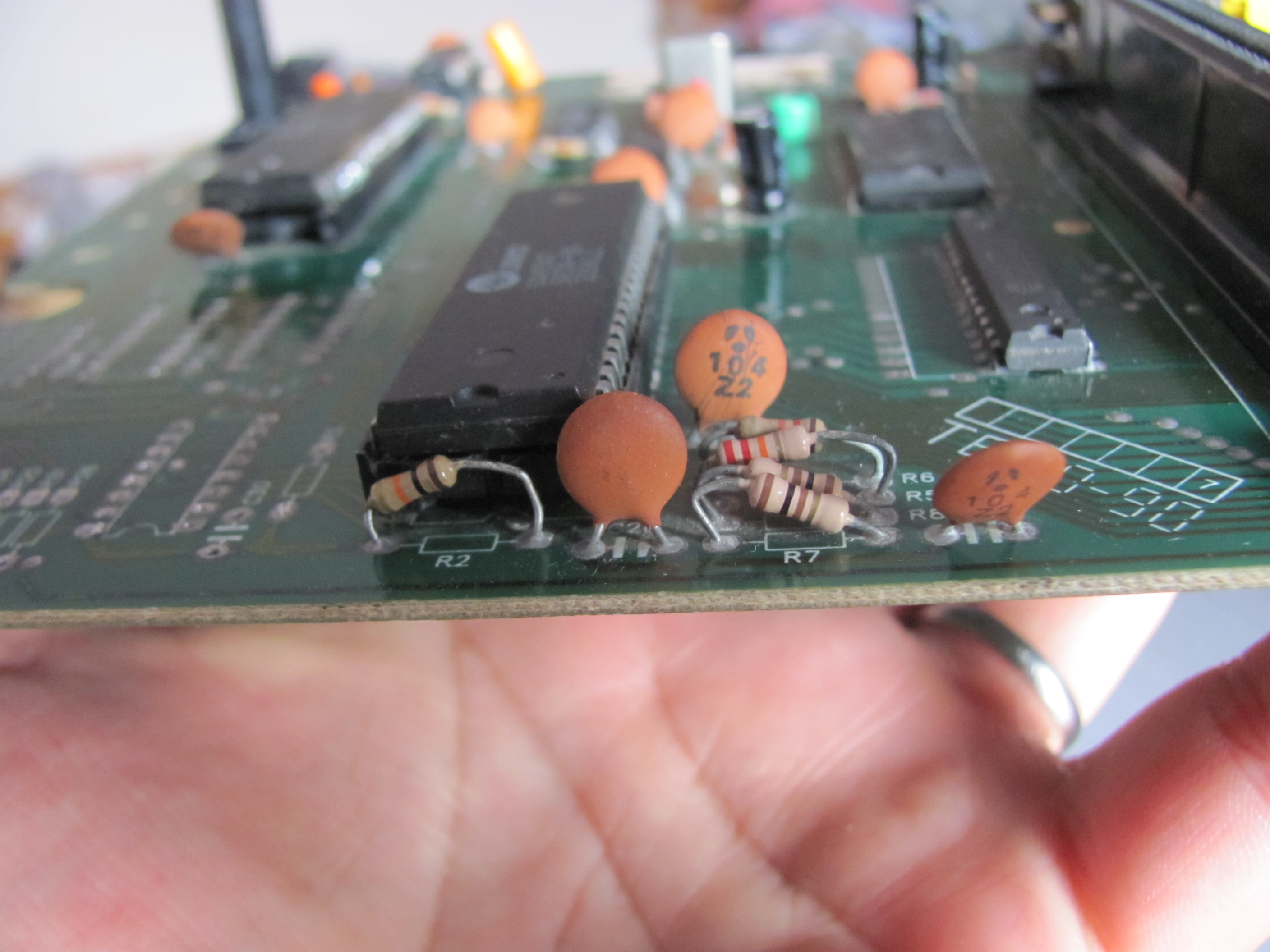
Here is a picture of the guy:
Attachment:
File comment: New old adapter
 20171028_101940.jpg [ 457.22 KiB | Viewed 3684 times ]
The only diference I noticed from this adapter to my other is the existence of this circuit:
Code:
__________
| C945P? | 22X (?)
|________| +---||----+
| | | | 10K |
| | +----+--/\/\/--+---> PPU A13
GND | 1K
+----/\/\/---> VCC
|
= 1mf x 35V
|
NES cart Pin 35
I think it's a CIC stun circuit, pretty common on old pirates back in the day.
I've put an X on the capacitor's last digit is because it's erased, also, the transistor's identification is not very clear.
I read what I could.
The capacitor (22X) is disconnected from the resistor on the transistor's side. If I connect it the game resets when I navigate through the pause menu.
I also tried to add a resistor that seemed to cure the reset issue on the adapter, but the only thing I got different was corrupted graphics.
I also tried to take off some pullup resistors on the console's motherboard, but the only one that I could see a diference was the in the CPU's /IRQ pin.
Without it, the game didn't boot at all. So, I've put it back.
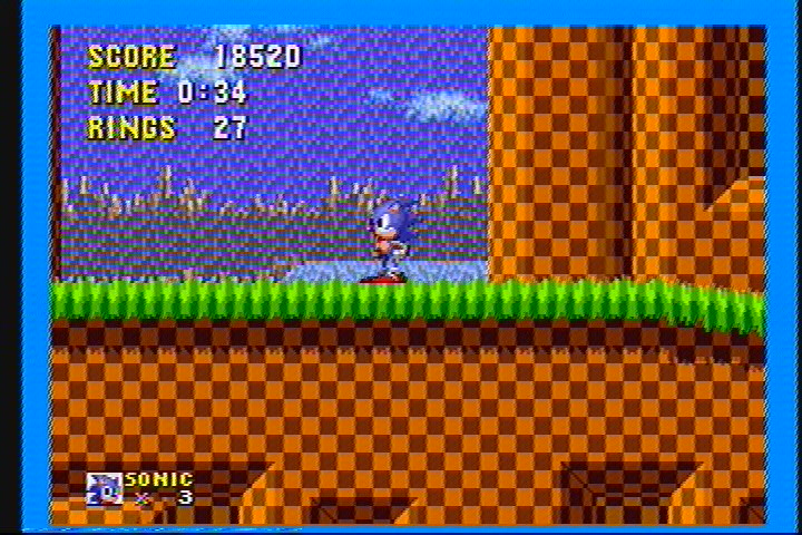
Just in case someone is curious on how it crashes on clashman's stage, I've
made a video of it.
Hope someday I can finally solve this issue.
Thanks in advance!
Well, I'm not surprised at all...
As I related in
this post, I made a Crisis Force repro.
Unsurpringly, the game just crashes in this clone.
It seems to be random. Any clues on how to debug it?
Maybe measuting the tensions on the WRAM chip can give some clues??
The only differences I can see between this clone, the other clone that works and an NES/FC schematics is that the clock generation is made with 2 transistors, instead of 2 not gates.
Could this be the cause of the whole mess??
For now I have 3 games that crashes, any suggestion of some more I could try to see what happens?
Curiously the pirate Gradius 2 I have works just fine.
Again, I'm supposing a new possibility and asking if it makes sense:
On the clones that the games works as in the original NES and Famicom, the clock generator is made using basically 2 transistors and a Xtal.
In this clone that I'm having trouble it uses 2 not gates to generate it's clock.
Could this be the issue? Some thing going out of sync?
Also, the PPU clock comes from one transistor while the CPU comes from other.
What's the other transistor doing to the clock? Is it inverting it or it's just buffering?
Maybe I should try to replicate the original NES' clock generator as close as possible and see what happens...
Some more news!!
First, I tried to socket the WRAM and have the same results.
Even with 3 different SRAM chips
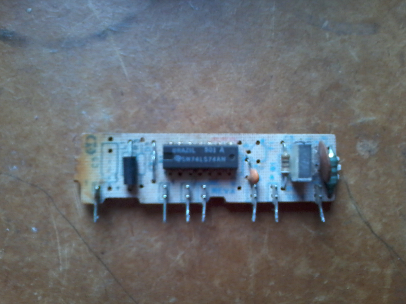
Them, I tried to build another clock generator and substitute the actual one.
I ended like this:
Attachment:
File comment: New Clock Gen
 4550c658-0449-4e34-a458-6bad5736c555.jpg [ 180 KiB | Viewed 3533 times ]
At first it seemed to be the deal, I was playing Crisis Force and everything was smooth.
Them the game froze for about a second, but continued. Weird!!
But when I arrived at the part near the 1st boss where the floor opens, it crashed!
I tried Megaman 2, and got he same Crashman's crash. Gradius was the same thing too.
So, with no other ideas, I just tried an original NES CPU I have from that flooded NES.
Intestingly, the games worked flawslessly!! Only Gradius is still giving me trouble.
By the logic, the problem would be on the clone's CPU.
I tested it on the other clone and again, it worked flawlessly! This time even Gradius worked fine.
Taking a better look at Gradius' board, after supposing it was some kind of protection related to the diodes that some of original famicom boards use without success, I noticed the the 74'161 pin 3 is with a steady voltage of 0.8V on the Phantom System, while in the other clone the same pin gets a voltage of around 4,5 volts.
I think this means that D0 is getting pulled to the logical level 0 on the Phantom System, while in the other clone it's floating, as it should in normal operation.
I tried some pullups on this pin and all that I could get was a non working game, that was cured as soon as I removed the resistor.
Could this possibly be ralated to a bus conflict?
Interstingly, there's an empty space on the board wich ressembles a 14pin IC and is like this:
Code:
O O--Vcc
|
/ROMSEL--O O
O O
|
O O
CPU R/W--O O
PRG /CE--O O
GND------O O
The PRG /CE pin comes from the PRG epoxy ROM and is bridged to /ROMSEL. The other pins (including /ROMSEL) come from the cartrige edge connector.
I just could not imagine what IC should be put in there to possibly avoid bus conflicts, any suggestions?
Looks like I should try to cut the PRG ROM's /OE and add an inverter to R/W on it. Could this possibly solve the problem?
I just don't understand why this happens with an clone and not with another.

I thing this is really weird!! How come this stuff have trouble just like this!!?
I really hope that someone that is reading this can help me to throw some light on it, at least the Gradius problem...
Anyway, the problems are almost all solved! And I sincerelly hope that this discussion can be useful to someone else in the future.
Sorry for this big wall of text...
Thanks in advance.
Edit:
Pictures of the Gradius' PCB.
Unfortunatelly it's not mine, but it's the same model.
Attachment:
 Gradius cce - Componentes.png [ 1.09 MiB | Viewed 3522 times ]
Attachment:
 Gradius cce - Solda.png [ 1.27 MiB | Viewed 3522 times ]
Mine is without the transistors and resistors, I added 2 diodes and is a lot more wornout.
Fisher wrote:
Interstingly, there's an empty space on the board wich ressembles a 14pin IC and is like this:
Code:
O O--Vcc
|
/ROMSEL--O O
O O
|
O O
CPU R/W--O O
PRG /CE--O O
GND------O O
[...]
I just could not imagine what IC should be put in there to possibly avoid bus conflicts, any suggestions?
That's for a 74'00.
pins 1,2, 3 -> invert /ROMSEL, generate +ROMSEL.
pins 4,5,6, evaluate NAND(+ROMSEL,+READ) → PRG/CE is only low if both ROMSEL and READ.
lidnariq wrote:
That's for a 74'00.
Thanks! That was it.
Unfortunatelly that didn't solve the problem
Now I'm sure it's not a bus conflict.
Just in case there's someone interested, i got p0rn pics from this board.
It is with the epoxy blobs, since I still want to make it work perfectly one day...
Attachment:
File comment: Component Side
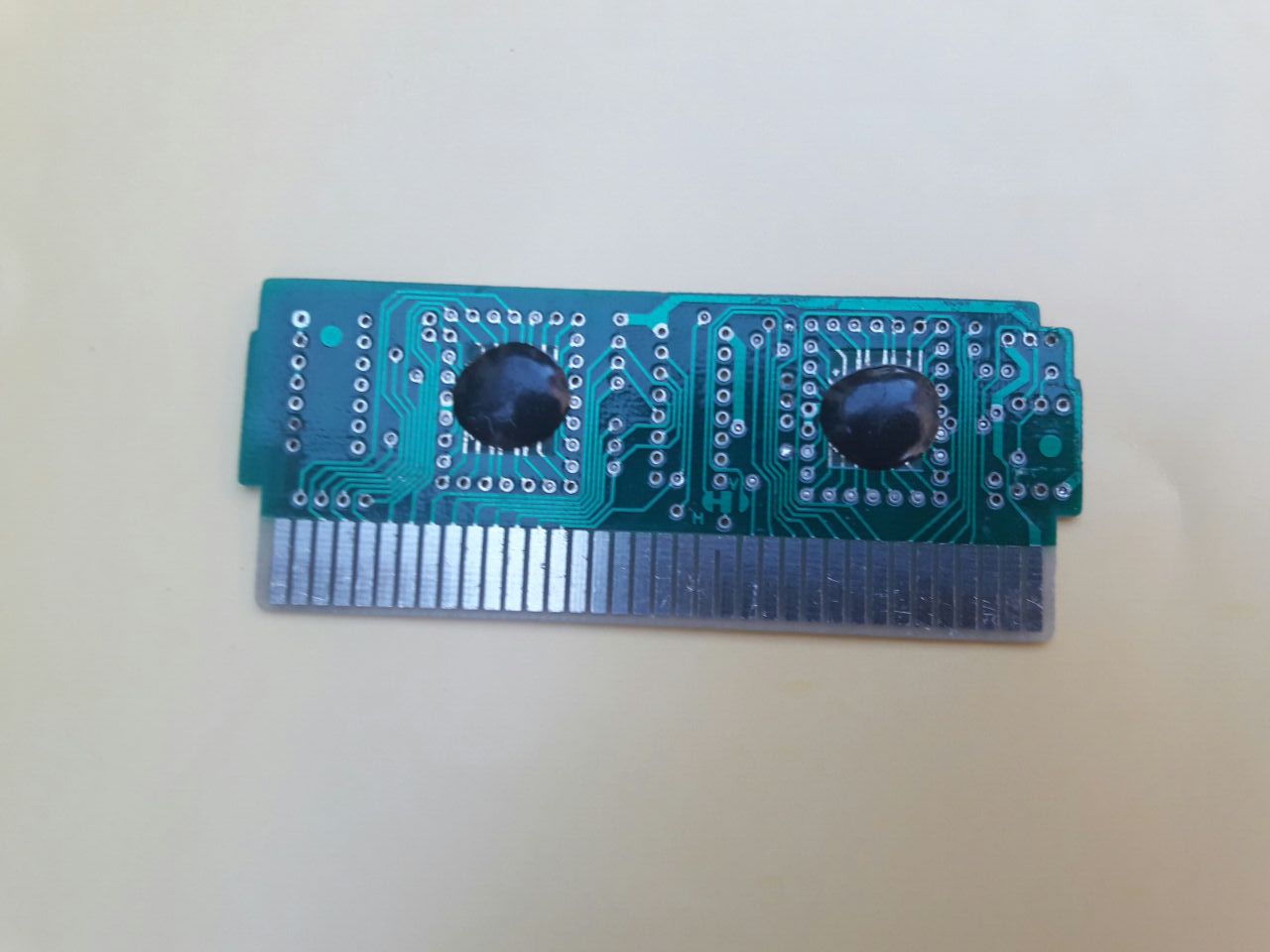 d2de435d-e068-4678-94fd-e8db99dea051.jpg [ 83.81 KiB | Viewed 3479 times ]
Attachment:
File comment: Solder side
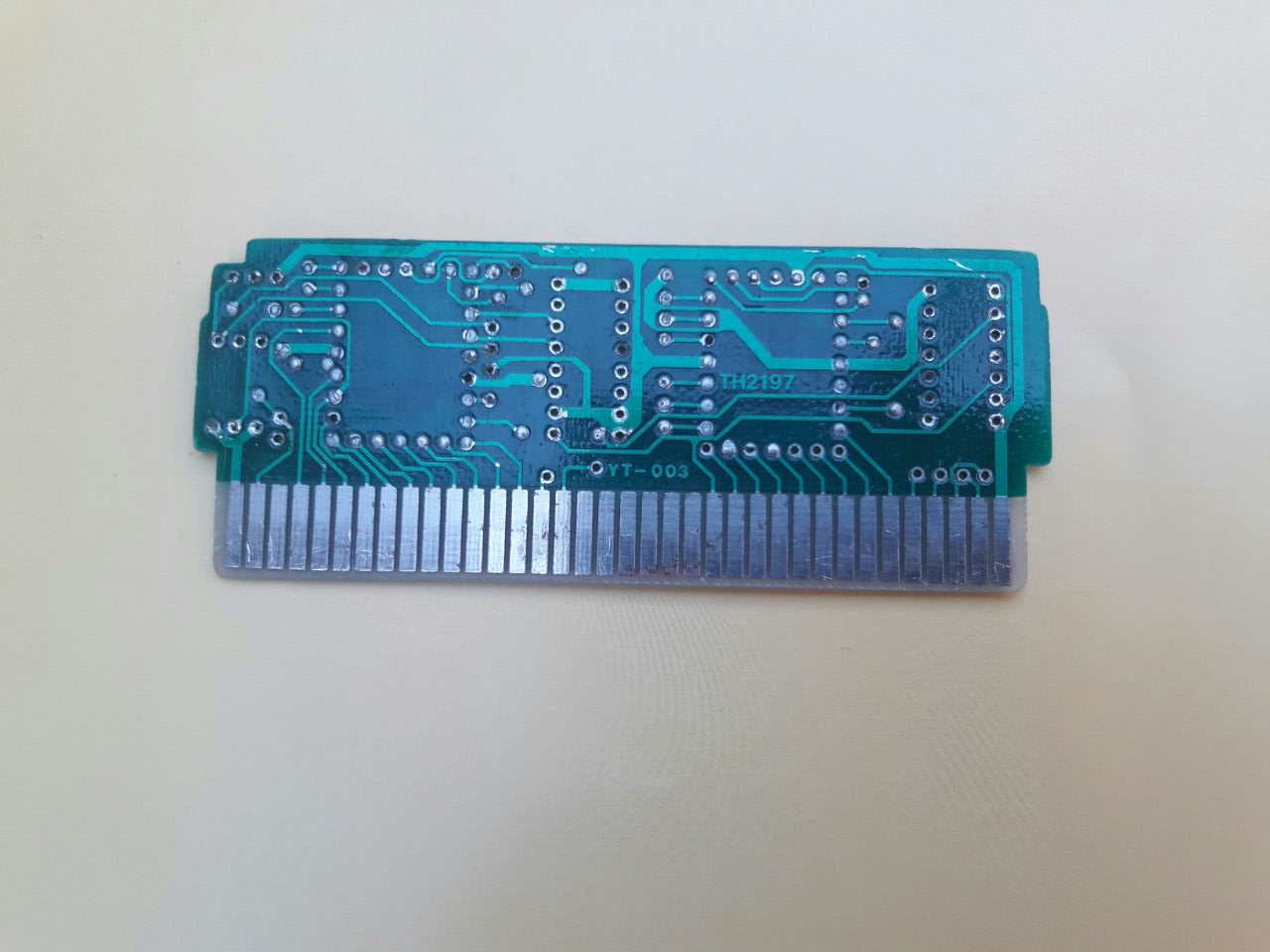 5b9c091f-18c6-45b0-a407-89d3a19561b4.jpg [ 100.84 KiB | Viewed 3479 times ]
Interestingly the component side is placed on the back of the cartridge, while the solder side faces the cartridge's label.
If someone can try to throw an educated guess of what kind of transistors the CIC defeater circuit uses I'll also be glad, since I got this board without this circuit parts.
I also tried it with the GameGenie, same deal...
If someone have an idea, please, share.
I read somewhere that circuit generator for crystal cannot be built using HC (CMOS) gates, there must be LS (TTL). Somewhere in time when I was tempted to build generator for my famicom i wanted to use gates due to less elements but I failed. The only trusting generator that always work is the 2 transistor one, from famicom schematics.
There are two transistors to buffer the signal and minimize interferences between them.
Also, I see you use sockets. When I bought lot of CPU/PPUs from aliexpress, I tested every one (using ZIF socket). Almost half of them did not work and I put them into `broken` parts bin. After some time I got idea of cleaning the pins with sharp knife to remove oxidation and most of the non-working chips started to work.
The nature of your problem sounds like somethink is floating and after time it get noise which breaks it. Maybe IRQ/NMI inputs of cpu are not pulled to VCC? Try also replacing PPU.
If you have chip tester (for example TL866), check if all those 74 chips from console are OK.
---
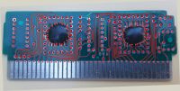
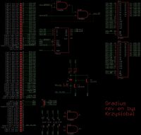
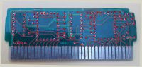
Now the lockout - I would assume both are NPN with ECB pinout (for example 2S945).
It produces negative voltage spikes.
When PPU-D1=5V, T1.B = 0.7V, T1 is saturated, T2 is cut off, upper terminal of C1 gets preloaded through R1 to 5 V (so C1 preloads to 4.3V)
When PPU-D1=0V, base of T1 does not gets any more current and T1 becomes cut off, T2.B=5V, T2 becomes saturated, upper terminal of C1 drops to ~0V (C1 is preloaded to 4.3 from previous cycle), so lower terminal of C1 (and thus output) goes to -4.3V (but C1 is quickly discharged throught R2 and maybe because of breakdown voltage of T1.EB
Here is simulation:
Thanks Krzysiobal!
It was a great help and I've restored the cartrige as it was, or what it should have been.
Not that it matters much, but...
I haven't test the output of the CIC defeater yet, but I think it should be just fine.
About the problem on the clone, except for testing every individual chip (since I don't have a tester), I've done everything you recommended.
I've exchanged all the socketed chips, including the CPU and PPU. I tried many combinations of the 3 couples I have and got the same results.
However I didn't test the CHR RAM and the latch, but I think the chances that they're involved with the problem are abysmal, aren't they?
I checked the pullups. They're there, they're showing continuity on both ends (VCC and CPU pin) and they're 10K. Should I lower them?
About the clock generator, I tried again the "spider" I've built with the same results.
I also cleaned the sockets and the chips. I remade some suspicious solder joints too, but again, no deal.
I really think that it must be something related to the PCB or some bad soldering, but just can't find exacly where it is.
Just by curiosity, I used TapeDump to dump the cartrige.
The NES file I've got ran fine on Nestopia and FCEU.
I think it's not fine fo post the ROM here, so, that's the CRC32 I've got:
Code:
GRADIUS.NES = c1c040bf
GRADIUS.CHR = de963bec
GRADIUS.PRG = 25e485b8
I took a look at BootGod's site and find no Gradius version with matching CRC, weird!!
Could it be an undumped version? I don't know how to take a look at goodNES database
By the title screen I think it's a japanese version:
Attachment:
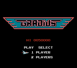 GRADIUS-0.png [ 2.28 KiB | Viewed 3376 times ]
I used the same console that are giving me problems to dump.
For curiosity, I've padded the PRG ROM to 256kB, wrote to a flash and used my UNROM test board to boot it.
Except for the graphics corruption, the game ran fine.
I didn't played the game to the end either on an emulator or on the "new" flash.
This is getting even weirder!!
CHR is unchanged-
http://bootgod.dyndns.org:7777/profile.php?id=1569To search by CRC32, select [Search] / [ROMs] / [CRC-32 / SHA-1]
lidnariq wrote:
CHR is unchanged
My bad!
Since I got the Konami one Gradius ten message, I assumed the CHR was edited.
Maybe I misunderstood the meanings...
Attachment:
File comment: Konami one
Gradius ten
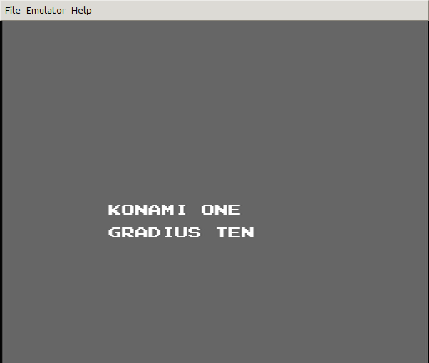 Gradius test.png [ 5.43 KiB | Viewed 3344 times ]
Or the ROM was (badly) edited...
Looks like my brain is not very multitask friendly, since I totally forgot I can generate an IPS patch to share the modifications made in the ROM.
I think that putting the file here won't be troublesome, at least not as posting the full ROM:
Attachment:
 GRADIUS.ips [37 Bytes]
Downloaded 92 times
GRADIUS.ips [37 Bytes]
Downloaded 92 times
To be sure of the file's integrity:
Code:
Original file:
Gradius (J).nes, CRC32 = 97c4eac3
Resulting file CRC32 = c1c040bf
Again, I'm out of ideas...
Is it a problem with the clone or with the cartrige?
Maybe the ROM is just a bit slow and something on this clone's board design makes this bug appear...
If I remember correctly, when this board was given to me years ago it was on the "works sometimes" bin.
I can try to get in touch with the guy who gave it to me, but I doubt if he would remember something about this.
As the Konami logo and the copyright text are missing, that
Gradius cart is indeed a hacked game.
I agree.
If I've looked at the PRG correctly, it has 22 zeroed bytes.
Code:
Address Original Pirate
00000734 61 00
00000736 0E 00
00000737 05 00
00000738 0F 00
00000739 02 00
0000073A 03 00
0000073B 11 00
0000073D 31 00
0000073E 39 00
0000073F 38 00
00000740 36 00
00000CC2 C0 00
00000CC3 C1 00
00000CC7 C0 00
00000CCB D0 00
00000CCC D1 00
00000CCD D2 00
00000CCE D3 00
00000CCF D0 00
00000CD0 D1 00
00000CD1 D2 00
00000CD2 D3 00
I'm not sure if all them are to erase logo and copyright information.
I just don't understand why all this work.
Would this make the piracy harder to spot?
Great!!!Every rom is useful
Fisher wrote:
I just don't understand why all this work.
Would this make the piracy harder to spot?
It's just common practice (used to be, at least) for crackers/hackers/pirates to change or blank out copyright texts (or adding something like "cracked by your captain sparrow!"), even though this may not really help hiding the blatant act of piracy(actually it DOES help, when the pirated games are distributed to places where people are less aware of such info., ESPECIALLY in places where console clones dominate the market, that people may not even know about the original systems).
Also, Gradius came with almost no protection, so it's really easy to hack, like
I've done 20 years ago.
Later games from Konami usually included harsher copy protections, which were usually triggered (especially) when someone tampered with their
copyright text.
So, what to try next?
I have some ideas, but I'm just short in time:
- Totally disassemble the clone's board, clean, check for bad traces and put it back together.
Very time consuming and possibly will take me nowhere.- Put a buffer on the PRG ROM's output controlled through /ROMSEL, in this case, i think the PRG ROM can be always enabled.
Good point since I probably can get the part from discarded boards but again, a high chance of unsuccess.- Write a new PRG ROM and put on place of that one.
Unfortunatelly, the smallest flash I could find is 64KB, wich will waste half of it if I do it.- Change the LS part to an HC part.
I doubt it would make such a big difference...- Ask someone to design and make another board that fits on the case.
Seems a good option, but probably would cost me money and I'm completelly broke - Buy an original oficial US NES.
I think it's the best solution, but again they're not cheap here and...- Forget this clone, take its cartridge connector out and put on the other clone that works.
It's a nice idea, since some games that have smaller edge connectors don't work properly on the other clone, also there's something weird in the other clone's sound path. Maybe it's missing a transistor...I really don't know what's the best thing to do.
Please, share your opinions.
Thanks in advance!!

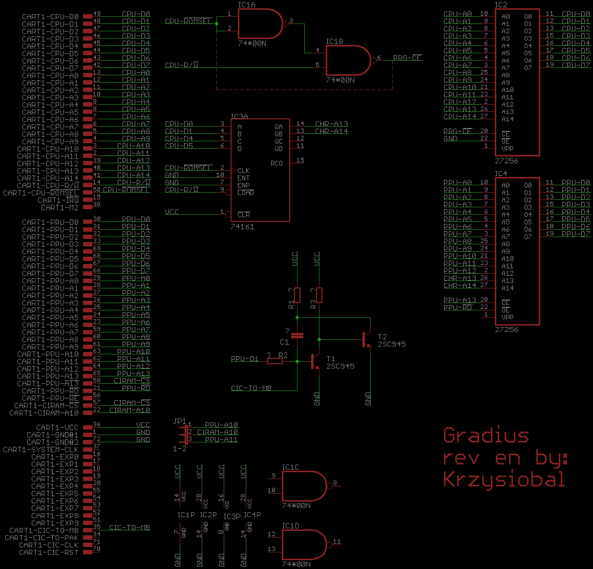
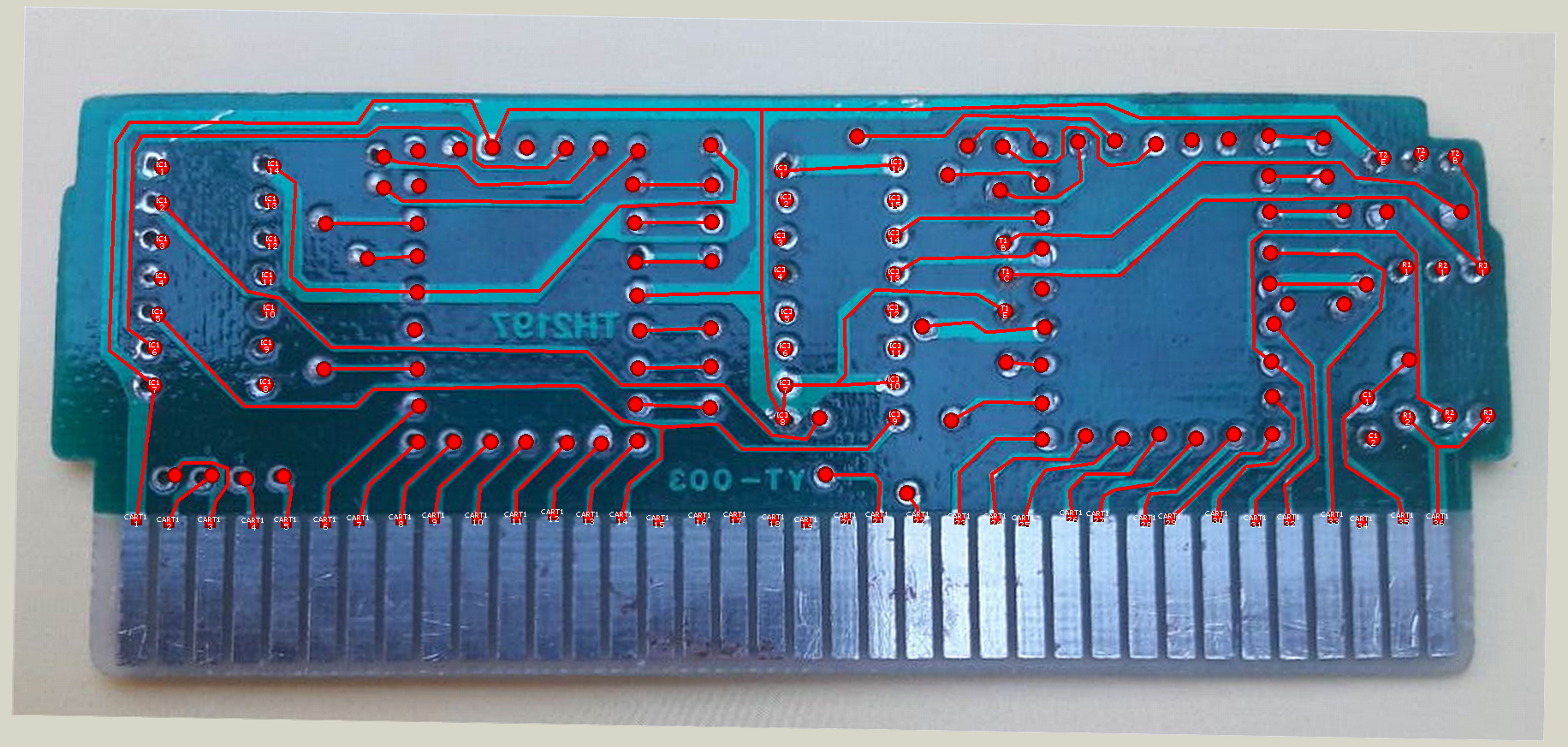
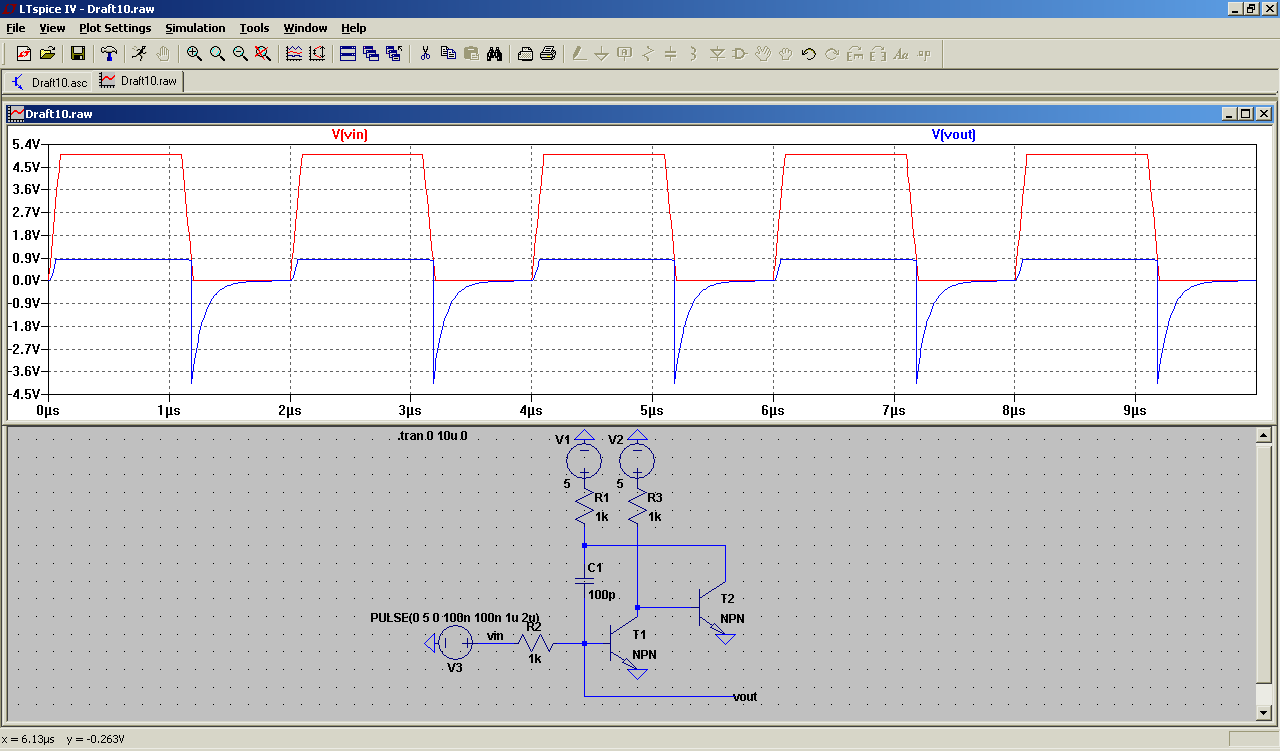
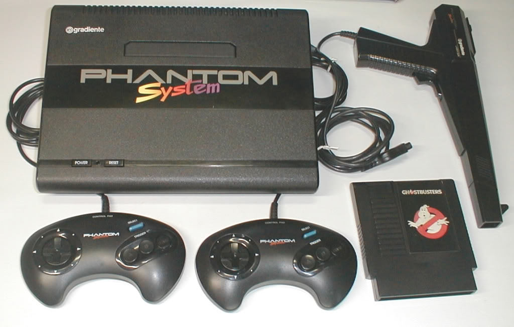
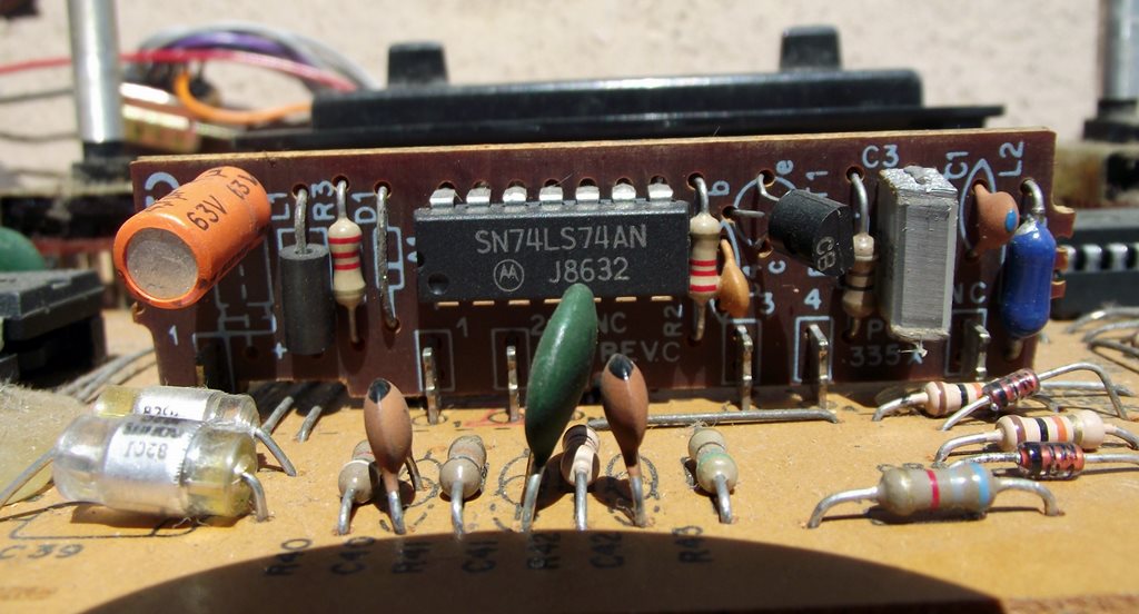