So, I've been trying to get a hold of many different people to acquire a couple copies of these... The relevant information that I have found on them is located here:
http://www.hardcoregaming101.net/korea/ ... y-open.htmhttp://sinfox04.egloos.com/6307944http://bbs.ruliweb.com/hobby/board/3001 ... derby=goodhttp://blog.naver.com/may517?Redirect=L ... 0126808705http://cafe.naver.com/joonggonara/239398180http://blog.naver.com/may517?Redirect=L ... 0130720337http://blog.naver.com/pollalla?Redirect ... 0110696361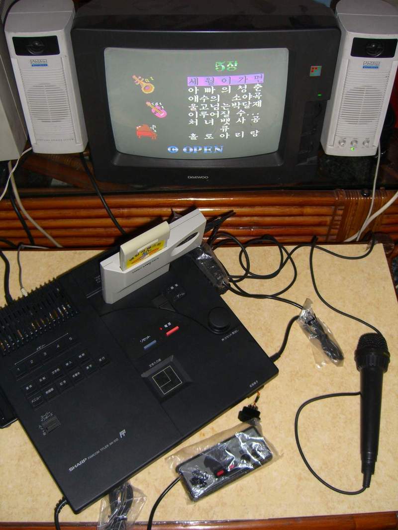
From what I can tell, it looks like a hardware unit with a detachable microphone and miniature cartridges like the Camerica Aladdin unit designed by Daewoo. It also has an FM sound chip inside of it. The software was designed by Open Corp; the same people who designed Buzz and Waldog.
I had a brief conversation with "sinfox04" but he does not speak much English and doesn't have much interest in parting with his unit.
Anyone else have more information regarding this product; or have easy access to Korean markets?
This looks a lot like the Famicom Titler to me. Never mind, I'm a dolt and didn't read carefully. You're talking about the cartridge, not the system

mikejmoffitt wrote:
This looks a lot like the Famicom Titler to me. Never mind, I'm a dolt and didn't read carefully. You're talking about the cartridge, not the system

It looks like they came packaged two ways:
With the Noraebang (Karaoke) unit stand-alone:
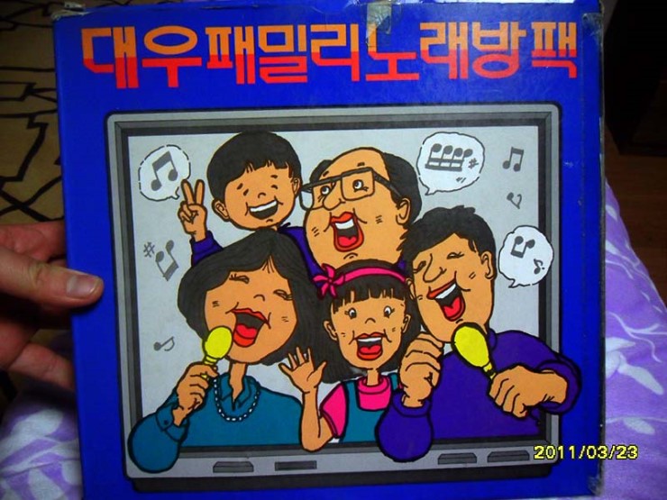
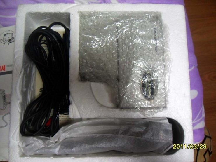
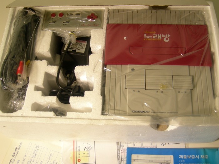
And included with a Famiclone (also by Daewoo):
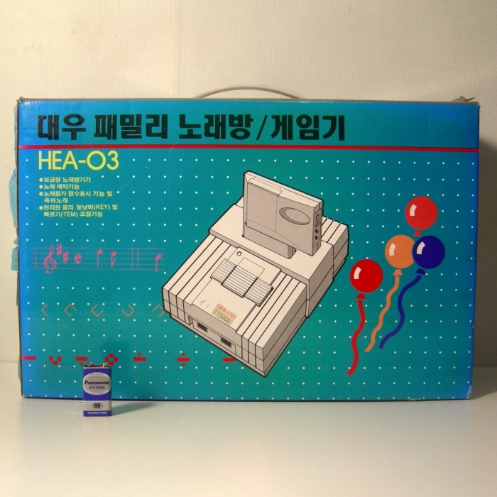
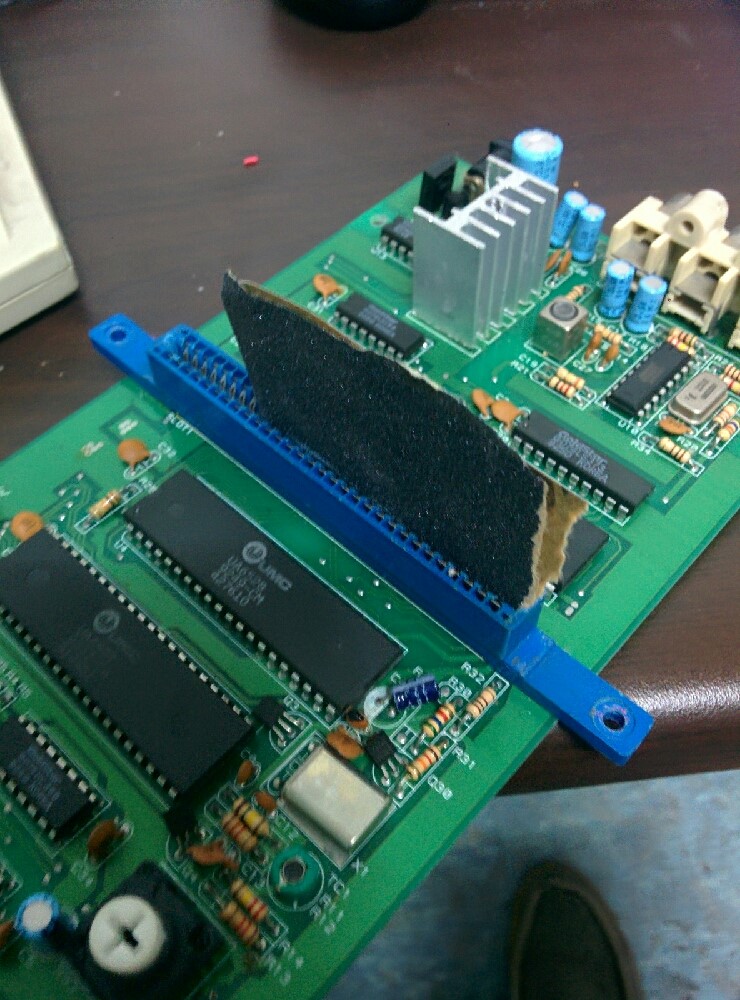
It appears that the Daewoo Famiclone used some of the same chips that the Dendy did; a UA6527 and UA6528:
And yes these things are hard to find plus expensive, even in Korea. There's another, way less known Karaoke cart by a company called Hicom.
Here's the PCB of that, if anyone is curious.
https://www.flickr.com/photos/151375036 ... ed-public/https://www.flickr.com/photos/151375036 ... ed-public/
Fantastic news! Hrm... Those pictures aren't high-resolution enough to make out what's inside of them. :/ It also does not appear to look like the unit?
Well... The goal is to get the whole thing emulated. I was considering the fact if it needed to potentially be destroyed for science. Hopefully if we get better pictures and you get your hands on it, you can also figure out the mysteries.

Do we know the total amount of extension carts and which ones there are?
I mentionned this was the other Karaoke cartridge that was released in Korea. Much smaller cartridge and has 3 times the number of song. Also less popular because it came from a smaller distributor.
As for the Daou's one, there are 4 known ext carts.
Hrm... Interesting. So I'm not familiar with this other cartridge then. Destruction is obviously not the goal, but some chips cannot be dumped by desired means. I was just planning for "just in case."
Very interesting though! Is it the same program?
B00daW wrote:
Hrm... Those pictures aren't high-resolution enough to make out what's inside of them. :/
What? I mean, I can't RE it just from these pictures, but it's not because some of the part numbers are illegible.
Code:
74????? 74LS00 74LS138 ⅛"jack resistorpile
74LS161 GD4066 MC3403P
74LS139 74LS273 74LS273 moreresistors
maskrom 8KRAM
I can certainly take educated guesses at what's going on—e.g. the GD4066 probably allows for software-adjustable volume control of the microphone.
But the real problem (to me) is that I can't see the traces that are under the ICs, especially the DIP ones.
Dumping the chips won't be enough anyway, I'm positive this operates on a unimplemented mapper so you'd need to do hardware & software RE. So your best bet to get it dumped and emulated would be a person used to such items.
Add to that the necessary update to the emulator to provide mic input directly to the game as it expects it.
Not an easy task by any means.
And no, it's a completly different software. I do have a kazzo but I haven't done any attempt at dumping it because it obviously won't work on any common mapper (and it's the only Famicom game from this company so it's likely a singleton mapper).
I can take HD pics of the PCB if anyone needs/wants them. But I won't desolder any chip by myself.
I can also try to follow some traces with a multimeter but I got no time to do that at the moment.
OK... Well this is a secondary "Noraebang" item; and it's of interest as well, for sure.
Yeah! Might as well give us some more HD pictures of the cart and casing. That would be nice.

Do we know the name of this cart, the software maker, and hardware maker? Kazoo dumper or TapeDump may do the trick if we can figure out the mapping from pictures. Otherwise CopyNES is also a good solution.
My personal interest in the Daewoo cart is finding out the FM chip inside of it.
Title: Kkachi wa Norae Chingu
Developper/Publisher: Hicom (You can see their logo on the pcb in fact, solder side, bottom left)
Video:
https://www.youtube.com/watch?v=1LA1bjvaFiUI'm not singing on the video but you can hear me blowing in the mic like an idiot (

) at the very end of the recording. The audio output is fairly nice tbh.
Thank you! I see the page here:
http://www.hardcoregaming101.net/korea/ ... -hicom.htmSeems like this is a boolean sorta switch thing... The mic can tell whether or not air pressure is applied, then the signal is supplied to the cart. To emulate this we'd just also need to know which register value the mic is mapped to. Doubt it's the same as the Famicom mic?
In regards to dumping 까치와 노래친구 we would only need to dump the PRG and CHR ROMs.

No destruction would be necessary.
Kkachi-wa is dumped.
>KKachi-wa Norae Chingu (K) (Unl).nes
It was UOROM, thanks to NewRisingSun for the support.
Now if it is possible or not to figure out how to feed the ROM with the microphone input it expects is another question.
Let's debug it. PM me with details.
Thanks.
Looks like it's reading two different addresses and comparing them... It's reading from $6000 and $6001. (These are likely the Mic (Force/Volume) Input values. Not sure why it needs two just yet...) Did most of the debugging with No$NES. To emulate this, we'd have to figure out the hardware of the mic input and the values that are stored/read. I'm not the greatest at hardware, but we'd have to trace hardware address $6000 and $6001 to the cart, see what it's connected to, and maybe look up a datasheet on those components.
Looks like bit 7 of $8000 is also mic enable?
The game is a 512KB UxROM.
This looks like the mic reader routine:
Code:
CCED A5 00 LDA $00 // $00 address value starts as #$10 during karaoke
CCEF 85 01 STA $01 // set up bankswitching
CCF1 A9 80 LDA #$80
CCF3 85 00 STA $00
CCF5 8D 00 80 STA $8000
CCF8 8D 00 80 STA $8000 // mic enable? can't be 2MB PRG. ;P
CCFB EA NOP
CCFC EA NOP
CCFD AD 00 60 LDA $6000 // load mic input (a) byte?
CD00 6A ROR A
CD01 B0 40 BCS $CD43
CD03 A2 00 LDX #$00
CD05 86 67 STX $67
CD07 AD FF FF LDA $FFFF
CD0A AD FF FF LDA $FFFF // value of $FFFF is #$D3
CD0D CA DEX
CD0E F0 40 BEQ $CD50 // branch to other routine (not currently understood)
CD10 AD 00 60 LDA $6000 // load mic input (a) byte?
CD13 6A ROR A
CD14 90 F1 BCC $CD07
CD16 A2 40 LDX #$40
CD18 8A TXA
CD19 4A LSR A
CD1A 69 E7 ADC #$E7
CD1C A8 TAY
CD1D C8 INY
CD1E 30 FD BMI $CD1D
CD20 CA DEX
CD21 F0 12 BEQ $CD35
CD23 AD 01 60 LDA $6001 // load mic input (b) byte?
CD26 6A ROR A
CD27 B0 06 BCS $CD2F
CD29 E6 67 INC $67
CD2B EA NOP
CD2C 4C 18 CD JMP $CD18
CD2F AD 00 60 LDA $6000 // load mic input (a) byte?
CD32 6A ROR A
CD33 B0 E3 BCS $CD18
CD35 86 68 STX $68
CD37 A5 18 LDA $18 // value is #$01
CD39 09 40 ORA #$40
CD3B 85 18 STA $18
CD3D A5 1C LDA $1C // value is #$2C
CD3F 09 02 ORA #$02
CD41 85 1C STA $1C
CD43 A5 01 LDA $01 // value should still be #$10
CD45 85 00 STA $00
CD47 8D 00 80 STA $8000
CD4A 8D 00 80 STA $8000 // bankswitch?
CD4D EA NOP
CD4E EA NOP
CD4F 60 RTS
CD50 A9 00 LDA #$00
CD52 85 68 STA $68
CD54 85 67 STA $67
CD56 4C 43 CD JMP $CD43
CD59 A5 1C LDA $1C
CD5B 29 84 AND #$84
CD5D D0 5D BNE $CDBC
CD5F A5 11 LDA $11
CD61 29 78 AND #$78
CD63 D0 57 BNE $CDBC
CD65 18 CLC
CD66 A9 00 LDA #$00
CD68 A6 63 LDX $63
CD6A 30 02 BMI $CD6E
CD6C A5 63 LDA $63
CD6E A6 64 LDX $64
CD70 30 02 BMI $CD74
CD72 65 64 ADC $64
CD74 A6 65 LDX $65
CD76 30 02 BMI $CD7A
CD78 65 65 ADC $65
CD7A A6 66 LDX $66
CD7C 30 02 BMI $CD80
CD7E 65 66 ADC $66
CD80 C9 18 CMP #$18
CD82 90 0A BCC $CD8E
CD84 C6 63 DEC $63
CD86 C6 64 DEC $64
CD88 C6 65 DEC $65
CD8A C6 66 DEC $66
CD8C A9 18 LDA #$18
CD8E 85 4C STA $4C
CD90 4A LSR A
CD91 29 0F AND #$0F
CD93 85 4E STA $4E
CD95 A9 0C LDA #$0C
CD97 85 4F STA $4F
CD99 20 4A E9 JSR $E94A
Anybody have any more thoughts? (Edit: Fixed the offsets in the disassembly.)
Here's some footage.Can somebody help me dump this cartridge with a kazzo? Usually I don't ask publicly but I think the hardware is of interest to some people here.
I can provide NROM and uorom readouts by PM (it's giving some early signs of life on uorom. I guess there's some shared register or something?)
PCB photo attached.
Without having yet sit down to trace the images, the single '374 implies there's a single bankswitching register that contains (almost?) all of the state.
The PAL could hold some state also, and it may be hard to reverse-engineer what it's doing without desoldering it.
Just for reference:
the GM0832 is a "successive approximation ADC", the KA22134 is a "dual pre-power amplifier with volume control" and two power amplifiers, the K-633A is unknown.
It really looks like there should "just" be a 1 MiB UNROM dump. (The '374 and the SIP resistor work together to emulate UNROM)
All the other logic (e.g. the sound ICs) goes through the PAL, so reverse-engineering the rest will require describing the behavior the software expects, or desoldering the PAL.
PAL pinout:
Code:
M2 -> | 01 20 | -- 5v
A13 -> | 02 19 | -> to PRG /OE
A14 -> | 03 18 | -> to '374 /OE (buffered copy of A14?)
/RS -> | 04 17 | -> latch clock to '374
R/W -> | 05 16 | ?> D7
A0 -> | 06 15 | <> SPI Data to/from the ADC
A1 -> | 07 14 | -> SPI CS to the ADC
A2 -> | 08 13 | -> SPI clock to the ADC
A3 -> | 09 12 | -> K-663A chip enable
gnd -- | 10 11 | <- PRGA21
"K-663A" "Sound IC" pinout:
Code:
gnd -- | 01 18 | <> D1
D2 <> | 02 17 | <> D0
D3 <> | 03 16 | -- +5
D4 <> | 04 15 | ??
D5 <> | 05 14 | ??
D6 <> | 06 13 | ??
D7 <> | 07 12 | <- from PAL pin 12
X1 -- | 08 11 | <- R/W
X2 -- | 09 10 | <- A0
<watches the video> OH, there's an FM synth. The above is the same pinout as the
YM2413.
Sch, but no idea what's goin on here with analog part.
Those tracks near pot, under MIC/AUX jack and near R8, C5, R13.1 need confirmation. Btw what should be connected to the upper 45-pin header? Keyboard?
Yeah, there were too many parts hidden under the electrolytic capacitors for me to figure that out to my satisfaction either.
Datasheet for the GM0832 says its pinout is
Code:
/CS -> | 1 8 | -- Vcc
Ch0 -> | 2 7 | <- CLK
Ch1 -> | 3 6 | -> DOut
Gnd -- | 4 5 | <- DIn
and that it expects, after /CS falls, three configuration bits clocked in on rising edges (i.e. change on falling edge), one padding bit, and then will emit successive 8-bit conversion results serially, MSB first, until CS rises.
So ... Ch0 and/or Ch1 really should be connected to the microphone jack, somehow.
—
Code:
Btw what should be connected to the upper 45-pin header? Keyboard?
Expansion pack for extra songs. This is similiar to Bandai's Karaoke Studio.
—
MLX wrote:
Can somebody help me dump this cartridge with a kazzo?
So ... if you're starting with INL's script in arantius's repository ... and you actually get a real dump when you try to run it as uorom (i.e. the first 16 K don't just repeat over and over) ...
just try changing the bit that says
cpu_romsize = 2 * mega to say 8 instead of 2.
krzysiobal wrote:
Sch, but no idea what's goin on here with analog part.
Those tracks near pot, under MIC/AUX jack and near R8, C5, R13.1 need confirmation. Btw what should be connected to the upper 45-pin header? Keyboard?
Traces on R8 are wrong, C7.1-R8 is wrong. C7.1 goes to R6.2.
R4.1 to C6.1
C5.1 to R7.1
R13 is correct.
As for the dump, looks like it's the same whatever the size, so yeah, it's repeating the banks :/
So, the PAL is connected to /ROMSEL, A13, A14, M2, ... and A0, A1, A2, and A3. There could be as many as 80 different registers ... but my hunch is that A0-A3 are only for interfacing with the ADC.
Try changing the number in cpu_write(d, 0x8000, i); to 0x6000, 0xA000, 0xC000, and 0xE000.
It's also remotely conceivable that the hardware here could actually be mapper 180 (bottom bank fixed) instead of "ordinary" UNROM (top bank fixed)—the PAL could possibly put the bankswitch register contents in any combination of lower and upper halves.
You could PM me the NROM subset.
Ok, yeah, that's definitely something like UNROM.
I think I see. Try changing cpu_write(d, 0x8000, i); to 128+i
(It looks like 0≤i≤127 map to the external ROM on the option slot; 128≤i≤255 should be the internal ROM)
Additionally, it looks like the FM synthesizer is mapped to addresses $6000 and $6001.
(I bet PAL pin 19 is something like (0 if /ROMSEL=0 AND R/W=1 AND PAL11=1))
dump first 32K data. send me.
On the first try, thanks!! But no music. I guess this has to be fixed in the emulator or handled in a new mapper?
This definitely requires a new mapper. While it's quite similar to both UNROM and to Mapper 188 (which is basically UNROM plus a microphone), I'd be uncomfortable saying it's appropriate to designate it as a submapper of either. (On the other hand, if someone else has an opinion that it should be filed as a submapper, I'd be all ears)
And we don't know whether the K-633A is using the same patches as the YM2413; certainly we already have the precedent that the VRC7 uses different baked-in ones.
To get the expansion cart, put it in the cart and and dump using the original UNROM script, but scan for up to 32 * mega. The expansion cart (probably overdumped) will be the first 2 MiB of the dump; the upper 2 MiB of the dump will definitely be an overdumped copy of the base game. The resultant 4 MiB image will be an overdump, but you (or someone, anyway) could shave it down.
It'd be nice to verify whether the PRG bankswitching register is present all over the entire range from $8000 through $E00F. I'd hunch it is, but ... if you'd be willing to (and I know bothering with 32 dumps is ridiculous), would you try replacing the cpu_write(d,0x8000,128+i) with 8001, 8002, ..., 800E, 800F, A000, &c ?
(If the board designer was feeling particularly sadistic ... since the board decoding mask is $E00F, they could have hidden writeable registers at $2002, $200A, $4009, and $400D... and readable ones overlaying $4000-$4004, $4008-$400F. But I really doubt they were)
Well if anyone want the rom to try to implement the sound, they can PM me. I'll release it anyway at some point. Otherwise if it proves to be too complicated I'll send the cart to someone interested to RE it and emulate it fully.
I'll try your suggestions later today, have to find the time.
make an all out effort!!!
It uses the default YM2413 instrument set indeed. I have implemented it in Nintendulator as Mapper 515 (512+ plane since it's an Asian-only release). Will post Nintendulator source code and Mapper DLL later. Nintendulator's YM2413 emulation was so VRC7-specific that all rhythm mode emulation code had been removed, and had to be re-added for this game. All that is left for me to investigate is to fix an issue with the rhythm channels not playing properly after loading a save state.
Any idea what it does with the expansion cartridge? Do any still exist? Because if the expansion cartridge is for adding new songs, this might be a way to play custom YM2413 music, giving an excuse for implementing full YM2413 in something like FamiTracker.
I've got a few I'd like to see:
- "Bang Bang" by Jessie J et al., medley with "Le Freak" by Chic
- "Bang and Blame" by REM
- "Fireflies" by Owl City, medley with "Feuer frei" by Rammstein
The ROM seems to expect this behavior:
Code:
Mask: $E003:
R/W 6000, 6001: YM2413 clone (thank you NewRisingSun)
R 6003: [D... ....] - SPI (ADC) data
Mask $E00F:
W 8000: [RBBB BBBB] - R:0-select external ROM; 1-select internal ROM; B-select bank at $8000-$BFFF
$C000-$FFFF is always last bank of internal ROM
Mask not yet known:
W C002: [S... ....] - SPI (ADC) chip select
W C003: [K... ....] - SPI clock / ADC conversion clock
The strictest address mask possible is $E00F, per the hardware, but specific functions could be more lenient.
I'd really like to find out by how much, but ... we'll see what MLX says.MLX says that the PRG banking register cares about all seven address lines. How odd.
Interestingly, the game doesn't seem to ever explicitly drive SPI data; something must be pulling the node high in order for the SPI ADC to get its required "start" bit. (And then, since there's no obvious way to get the data line to change, it must be clocking in "1 1" for "single-ended conversion" and "pin 3=Ch1")
The ADC code is:
Code:
LDA #0
LDY #$FF
STA $C002 ; chip select falls
STA $C003 ; SPI clock falls
STY $C003 ; rises; clock in start bit here
STA $C003 ; falls
STY $C003 ; rises; clock in 1:Single or 0:differential here
STA $C003 ; falls
STY $C003 ; rises; clock in (Single:1:Ch1 or 0:Ch0) or (Differential:1:Ch1 minus Ch0 or 0:Ch0 minus Ch1)
STA $C003; falls
LDX #8
-
STY $C003; rises
STX $C003 ; falls; data now valid
LDA $6003 ; read data
ASL A
ROL $00
DEX
BNE -
LDA #$80
STA $C002 ; raise chip select
and it only runs at 60Hz.
The other interesting bit is that the cart
doesn't mix in the audio from the 2A03. All the sound can only come from the FM synthesizer.
—
To check for an expansion cart, the game checks for a sixteen-byte header ("OPEN FAMILY SONG") mapped at $8000 in the very first bank, and if present, will JSR to $8010. It's possible in intercept NMI partway through by feeding an invalid value to one of the jump table indexes (after it's already done a bunch of random other things). IRQs will cause a spinlock—the IRQ vector points to an RTI.
(issue resolved, see below post.)
All right. Here is my Nintendulator source file for this game, including my (awkward) attempt at Microphone level measurement. Since I don't actually have a microphone, I have tried to make the "MIC" display respond to a simple music line-in signal. It always reads the "wave mapper" device. Since Nintendulator by default does not yet support mapper numbers >255, I needed to change the source file responsible for that as well. I also needed to update the VRC7 emulator to allow for both original YM2413 and VRC7 instrument sets, and to get back the rhythm mode emulation code. The expansion cartridge is supported as well; basically, any PRG ROM exceeding 1 MiB is assumed to be expansion cartridge memory and must come at the beginning of the ROM image.
Compiled Mapper DLL
here.
NewRisingSun wrote:
All right. Here is my Nintendulator source file for this game, including my (awkward) attempt at Microphone level measurement. Since I don't actually have a microphone, I have tried to make the "MIC" display respond to a simple music line-in signal. It always reads the "wave mapper" device. Since Nintendulator by default does not yet support mapper numbers >255, I needed to change the source file responsible for that as well. I also needed to update the VRC7 emulator to allow for both original YM2413 and VRC7 instrument sets, and to get back the rhythm mode emulation code. The expansion cartridge is supported as well; basically, any PRG ROM exceeding 1 MiB is assumed to be expansion cartridge memory and must come at the beginning of the ROM image.
Compiled Mapper DLL
here.
thankyou
but MLX not send me rom....
Thanks to everyone the rom has been released

NewRisingSun wrote:
All right. Here is my Nintendulator source file for this game, including my (awkward) attempt at Microphone level measurement. Since I don't actually have a microphone, I have tried to make the "MIC" display respond to a simple music line-in signal. It always reads the "wave mapper" device. Since Nintendulator by default does not yet support mapper numbers >255, I needed to change the source file responsible for that as well. I also needed to update the VRC7 emulator to allow for both original YM2413 and VRC7 instrument sets, and to get back the rhythm mode emulation code. The expansion cartridge is supported as well; basically, any PRG ROM exceeding 1 MiB is assumed to be expansion cartridge memory and must come at the beginning of the ROM image.
Compiled Mapper DLL
here.
than you !!! Great! but nonwindows os....
Regarding the dumps on the Bootleg Wiki board, do we have all the expansion boards dumped? This is very exciting news!
Wondering the proper method to get an NSF rip of these now too...
Record them as VGMs

The hardware that they came from doesn't permit combining the YM2413 synthesizer sounds with the 2A03's sounds, so permitting them in an NSF is a little misleading.
On the other hand, maybe explicitly adding a YM2413 option into NSF would stop people from using the YM2413 as through it had the same patch set as the VRC7. Oh, who am I kidding?
Looks like the
ICs for K-663A are still being sold; and that they were used in other arcade cabinet games like
Mahjong Tenkaigen.
Wonder if the K-663A were decapped that it would present any differences?
The last I checked—and this could be stale—we didn't have die-extracted values for the YM2413 built-in patches either, so decapping and staining a K-633A wouldn't be sufficient to determine whether it were identical.
Also, the MAME source implies that the K-633A is a knock-off of the UM3567, which is itself a knockoff of the YM2413. I think it's possible that they could all have subtle differences in the patch set.
Here's a page in Brazilian Portuguese that has recording of both the UM3567 and the YM2413 and I don't hear any difference... but I wouldn't trust my ears to be anything resembling authoritative.
tepples wrote:
Any idea what it does with the expansion cartridge? Do any still exist? Because if the expansion cartridge is for adding new songs, this might be a way to play custom YM2413 music, giving an excuse for implementing full YM2413 in something like FamiTracker.
I've got a few I'd like to see:
- "Bang Bang" by Jessie J et al., medley with "Le Freak" by Chic
- "Bang and Blame" by REM
- "Fireflies" by Owl City, medley with "Feuer frei" by Rammstein
You can already use the full YM2413 in MML with NSD.lib and play it back on hardware with a TNS-HFX4.
The latest version of the PowerPak VRC7 plugin can swap into YM2413 mode as well.
Can you see from the PCB images whether there is a low-pass filter after the FM chip (or its DAC), and if so, what its parameters are?
There is a bunch of audio filtering, both low- and high- passes, but the electrolytics were big enough that both Krzysiobal and I gave up on trying to figure out what's going on.
Regardless, we couldn't see the sizes of the electrolytics in these pictures, so couldn't tell you the audio filtering corner frequencies regardless of whether we had a correct schematic.
I got from MLX a little bit different (older) version of this cartridge - there's minor difference in the analog part - less resistors, so I finally was able to rev-en it with proper values of elements.
They even splitted the GND between analog and digital circuits.
I will try to make repro of this board

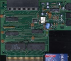
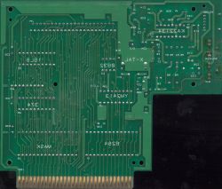
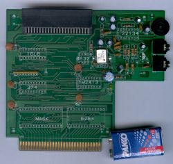
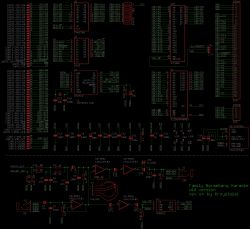
ROM CRC32 is 978002FD
I haven't put very much time in analyzing it, but it does not output microphone sound (and did not display volume level from it), so it probably has design flaw or something is broken.
I also dumped the pal:
Code:
------------------------------------------------------------------------------------
YM-!CE! = (!M2) | (!CPU-A13) | (!CPU-A14) | (!CPU-!ROMSEL!) | (CPU-A1);
0x6000 (mask: 0xE002)
------------------------------------------------------------------------------------
ADC-CLK = Probably non-combinatorial
------------------------------------------------------------------------------------
ADC-!CS! = Probably non-combinatorial
------------------------------------------------------------------------------------
ADC-D = (I14 & CPU-A1 & !CPU-R/!W! & !CPU-!ROMSEL! & CPU-A14) | (I13 & !CPU-A14) | (
I13 & !CPU-A1) | (I13 & CPU-R/!W!) | (I13 & CPU-!ROMSEL!);
Probably non-combinatorial
------------------------------------------------------------------------------------
CPU-D7 = (I13 & CPU-A1 & CPU-A0 & CPU-R/!W! & CPU-!ROMSEL! & CPU-A14 & CPU-A13 & M2) | (
I14 & !M2) | (I14 & !CPU-A13) | (I14 & !CPU-A14) | (I14 & !CPU-!ROMSEL!) | (
I14 & !CPU-R/!W!) | (I14 & !CPU-A0) | (I14 & !CPU-A1);
Probably non-combinatorial
------------------------------------------------------------------------------------
REG-CLK = (CPU-A1) | (CPU-A0) | (CPU-R/!W!) | (CPU-!ROMSEL!) | (CPU-A14) | (CPU-A13);
adr 1000000000000000 0x8000
mask 1110000000000011 0xE003
------------------------------------------------------------------------------------
REG-!OE! = (!CPU-!ROMSEL! & CPU-A14);
------------------------------------------------------------------------------------
PRG-!OE! = (!PRG-A21 & !CPU-A14) | (!CPU-R/!W!) | (CPU-!ROMSEL!);
------------------------------------------------------------------------------------
krzysiobal wrote:
ADC-CLK = Probably non-combinatorial
ADC-!CS! = Probably non-combinatorial
Given prior evidence, those should both latch the values written to the $80s bit at $C003 and $C002 respectively.
Quote:
ADC-D
I'd have thought there should be some way for the CPU to drive this node high ; the ADC requires that the first bit that's clocked into it be high (and, given how this is wired, also the 2nd bit).
Quote:
CPU-D7 Probably non-combinatorial
That's more surprising to me. As far as I can tell, it should "just" relay the value from ADC-D when (address&$E003)==$6003 (and be hi-Z otherwise)
Quote:
REG-CLK = (CPU-A1) | (CPU-A0) | (CPU-R/!W!) | (CPU-!ROMSEL!) | (CPU-A14) | (CPU-A13);
adr 1000000000000000 0x8000
mask 1110000000000011 0xE003
We know for certain that the later revision of this hardware also cares about A2 and A3 ... much to my surprise.
The K-663A can be replaced with YM2413, which can be still bought from aliexpress and it sounds the same (even better because when there is silence, the original K-663A produces buzz)
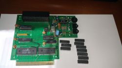
Of course you need to be quite lucky, out of 10 chips, 3 were bad: 1 did not output any melody at all and 2 others sounded like some channels were missing.
I read back the GAL using TL866 and then programmed other GAL16V8 using its contents and it's working, so probably it wasn't protected against writes.
Hm. I tried analyzing that fusemap using jed2eqn, and it complained. So I looked closer ... and it's using an operational mode that Lattice's datasheet doesn't define.
*L02176 100000011111000000
those last two bits are called SYN and AC0. Lattice only explains what 01, 10, and 11 mean.
National's datasheet
does mention that the two function independently:
The SYN bit controls whether a device will have any registered outputs (SYN=0) or will be purely combinatorial (SYN=1). The SYN bit determines whether device pins 1 and 11 are used as the clock and global TRI-STATE control inputs (SYN=0) or whether they are ordinary inputs (SYN=1). The AC0 bit selects between the "Small-PAL" mode and the "Medium/Registered-PAL" modes. The function of the AC1 bits depends on the state of the AC0 bit. In "Small-PAL" mode (AC0=0), the AC1 bit in each [output logic macrocell] determines whether the associated device pin is an output (AC1=0) or an input (AC1=1)
It then continues to give an example of permissible modes and also excludes the 00 combination.
SYN=0 means that pin 1=M2 serves as the clock, and pin 11=PRGA21 controls whether the outputs can serves as /OE ? Er. But:
AC0=0 means that all pins are always an input or an output and ignores pin 11.
Well, small wonder that the ADC doesn't work.
AC1 exists per output; there are 8 bits. Bits 2120 through 2127 are b'00001100'; this means the following:
Pins 19 & 12 are always an output, have 8 AND terms, the output of the register is not presented on the pin, but the output of the register is available inside the AND-OR plane.
Pins 18,17,16, & 13 are always outputs, have 8 AND terms, the output of the register is not presented on the pin, but the value on the next-higher-numbered pin is available inside the AND-OR plane.
Pins 15 & 14 are always inputs, have 8 AND terms, the output of the register would be presented on the pin, the value on the next-higher-numbered pin is available inside the AND-OR plane.
XOR exists per output; there are 8 bits. Bits 2048 through 2055 are b'01100001', meaning that pins 18, 17, and 12 are inverted relative to the logic from the AND-OR plane.
Meanwhile, the fusemap includes an 8-byte "user signature" in bits 2056 through 2119, which happens to be ASCIIZ: "GAL16V8\x0"
krzysiobal:
In regard to the K-663A, I see that it's used in certain bootleg arcade machines. I do not see any datasheets for it or who produces it. If you program it with all known modes of the YM2413 does it react in the same manner? Are there any registers outside of the normal YM2413 that behave differently?
Also I see that some chips in bootleg arcade units are labeled K-663.
Not much info on these...


