EPROM LPT Programmer?

This is an archive of a topic from NESdev BBS, taken in mid-October 2019 before a server upgrade.
View original topic
EPROM LPT Programmer?
by on (#202732)
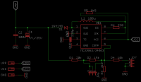
In order to learn some basic info about eprom programmer I want to make this : EPROMr

Image

Image

It seems that the source code of the software is not available, so I wrote my own :

Code:
#include <stdio.h>
#include <dos.h>

void main ()
{
   long int i;

   outportb ( 0x37A, inportb(0x37A) & 254 );      /* Set reg0 [pin1] to low >> set reset to high */
   outportb ( 0x37A, inportb(0x37A) | 1 );         /* Set reg0 [pin1] to high >> set reset to low */

   FILE *fp;
   fp=fopen ("read_eprom.bin", "wb");         /* Create a file to store data of eprom */

   for ( i=1 ; i<=1048576 ; i=i+1 )         /* 1048576 dec = 100000 hex */
   {
      putc (inportb(0x378), fp);         /* Read eprom data and save it to the file */

      outportb ( 0x37A, inportb(0x37A) | 4 );      /* Set reg2 [pin16] to high >> set clock to high */
      outportb ( 0x37A, inportb(0x37A) & 251 );   /* Set reg2 [pin16] to low >> set clock to low */
   }

   fclose(fp);
}


But I haven't tested it yet.
Do I have to use any delay between clocks inside of the for loop?
By the way my code is only for 27C080 (1MB) EPROM.
Re: LPT EPROM Reader?
by on (#202737)
Use Atmega32+VUSB instead of crappy old slow LPT with unknown response times.
Unless you use pure realtime DOS.
Re: LPT EPROM Reader?
by on (#202739)
That's great Farid!!
Thanks for sharing!! Now I have another reason to try to build this burner. :D
Unfortunatelly, I don't think this will compile under Linux... :cry:
Maybe with some small modifications.

@Krzysiobal:
I don't know much about the inner workings of the paralel port, and I really think there are better options around.
But it seems very simple and inexpensive to use it.
Back in the day there was many stuff that successfully used it.
I've even been using an N64's GameShark inside a Win98 virtual machine without issues.
Maybe it's because I'm still using a PC wich have an onboard paralel port...
By the way, I think the gamecon driver rocks!!
Re: LPT EPROM Reader?
by on (#202749)
FARID wrote:
Do I have to use any delay between clocks inside of the for loop?
Access to these I/O ports is often really slow. Your code will assemble into several INB and OUTB instructions and the last time I tried this I wasn't getting faster than ~500ns per write.

You probably don't need to add anything.
Re: LPT EPROM Reader?
by on (#202756)
krzysiobal wrote:
Use Atmega32+VUSB instead of crappy old slow LPT with unknown response times.
Unless you use pure realtime DOS.

I try to keep it in my mind for future projects, but for now I want to keep this thing as simple as possible.

Fisher wrote:
That's great Farid!!
Unfortunatelly, I don't think this will compile under Linux... :cry:
Maybe with some small modifications.

Here is a code for linux : https://outflux.net/software/pkgs/EPROM/
Hardware info : https://outflux.net/software/pkgs/EPROM/mirror/

lidnariq wrote:
Access to these I/O ports is often really slow. Your code will assemble into several INB and OUTB instructions and the last time I tried this I wasn't getting faster than ~500ns per write.

How fast is it possible to access an EPROM to read or write it?

I modified the schematic to work with my code, does it look ok?
Re: LPT EPROM Reader?
by on (#202759)
FARID wrote:
How fast is it possible to access an EPROM to read or write it?
If you have a tight assembly loop, you can probably get a read speed of not more than ≈2MHz? Random projects implementing parallel port logic analyzers show speeds roughly around that.

Remember that you have to configure your parallel port to use its data pins as an input, not an output. How depends on whether the port is running in "Bidirectional", "ECP", or "EPP" mode. Depending on things, you might find it simpler to use the status pins and control pins to accept input from the ROM instead of the data pins, and instead use the data pins to reset and clock the counters.

Schematic looks like it matches your code.
Re: LPT EPROM Reader?
by on (#202838)
Well It didn't work! :cry:
So this is way too tough than it seems at first even for a simple read operation!
Here are some notes I found out from googling :

I have to use only EPP mode and not SPP or ECP.

Reg5 of Control pin is used for Enabling Bi-directional mode for D0 ~ D7 [pin2 ~ pin9]. So I have to set it to 1 to enable this feature.

Before you can start any EPP cycles by reading and writing to the EPP Data and Address Ports, the port must be configured correctly. In the idle state, an EPP port should have it's nAddress Strobe, nData Strobe, nWrite and nReset lines inactive, high. Some ports require you to set this up before starting any EPP Cycle. Therefore our first task is to manually initialise these lines using the SPP Registers. Writing XXXX0100 to the control port will do this.

The Status Port has one little modification. Bit 0, which was reserved in the SPP register set, now becomes the EPP Time-out Bit.
The EPP Timeout bit we have already discussed. When this bit is set, the EPP port may not function correctly. A common scenario is always reading 0xFF from either the Address or Data Cycles. This bit should be cleared for reliable operation, and constantly checked.

Image

1. Program reads EPP Data Register. (Base + 4)
2. nData Strobe is asserted if Wait is Low (O.K. to start cycle)
3. Host waits for Acknowledgment by nWait going high
4. Data is read from Parallel Port Pins.
5. nData Strobe is de-asserted.
6. EPP Data Read Cycle Ends.

Visual Basic for Electronics Engineering Applications : page 419 :
Quote:
The control signals used to perform the bus cycles are fairly simple. As a
example, consider an address write cycle. To begin an address write cycle, the
host places an 8-bit address on_ADO-AD7 and pulls Write (indicating that the
host is doing a write operation) and AStrb (indicating that the information on
ADO - AD7 is an address) low. The peripheral device corresponding to the
address responds by setting Wait high to indicate that it recognizes it's being
addressed and is ready to receive the address byte. Upon seeing Wait go high,
the host de-asserts AStrb. This action signals the peripheral to read and store the
byte on ADO-AD7 to use as the register address for following data cycles. The
peripheral then pulls Walt low to indicate that it's ready for a new bus cycle, and
the host ends the current bus cycle by removing the signals from ADO-AD7 and
setting Write back high.
A data read bus cycle proceeds in much the same manner. The Dstrb and Wait
lines are the handshake signals that coordinate the data transfer, and the state of
the Write line determines whether the bus cycle is a read cycle or a write cycle.
Re: LPT EPROM Reader?
by on (#203516)
Now I feel that EPROMr doesn't use the real EPP handshake.

It seems that EPROMr (and it's other mods) uses SPP and tries to generate the handshake signals manually by using the software.

Here is the summery of the pin function for different projects of EPROMr :

EPROMr v1.0
Pin1 ==> Reset
Pin14 ==> Clock-hi
Pin16 ==> Clock-low

EPROMr v2.0
Pin1 ==> Clock
Pin14 ==> Reset
Pin16 ==> /GVPP

EPROMr 27C801 v1.0
Pin1 ==> Clock
Pin14 ==> Reset
Pin16 ==> /GVPP

EPROMr 27C801 v2.0
Pin1 ==> Clock
Pin14 ==> /CE
Pin16 ==> Reset
Pin17 ==> /GVPP

While according to this reference I feel in order to use the real EPP handshake the pin functions must be :
Pin1 [Output /C0 Write] ==> EPROM /GVPP
Pin11 [Input /S7 Wait] <== Can be generated with Q0 of 4040 :idea: ?
Pin14 [Output /C1 Data Strobe] ==> 4040 Clock
Pin16 [Output C2 Reset] ==> 4040 Reset
Pin17 [Output /C3 Address Strobe] ==> EPROM /CE

Image

Please let me know if I wrong :?:
Re: LPT EPROM Reader?
by on (#203525)
Unfortunately, I've never done parallel port projects that went beyond the capabilities of the SPP.

Certainly the thing you've describes as "EPROMr 27C801 v2.0" uses the parallel port in SPP mode.

Are you specifically trying to support programming the 27C801 ? It'd be much easier if you didn't.

Looking for information, I found a example "breakout" schematic that basically shows the EPP as nothing more than two multiplexed 8-bit bidirectional ports via the standard pinout. Think of pin 1=/C0=/Strobe as "Read//Write", and /AddrStrobe and /DataStrobe as inverted forms of NES's +M2.

For read-only, you want something more like
Pin 1 = /C0 = Read//Write = /Strobe → inverter → EPROM Vpp//OE
Pin 11 = /S7 = /Wait = /Busy ← inverter ← RC delay from /DataStrobe (should be set to match the ROM's access speed)
Pin 14 = /C1 = /DataStrobe = /ALF → EPROM /CE and also '4040 clock
Pin 16 = +C2 = /Reset = +Init → what you said
Pin 17 = /C3 = /AddrStrobe = /SelP — unneeded

Programming is a bit more complicated, because the UVEPROM programming protocol requires reading and writing the same address repeatedly until either the data read back matches, or it times out.
Re: LPT EPROM Reader?
by on (#203600)
Quote:
Are you specifically trying to support programming the 27C801 ?

For now I am testing it with AT27C080

Quote:
It'd be much easier if you didn't.

What do you mean?

lidnariq wrote:
Pin 11 = /S7 = /Wait = /Busy ← inverter ← RC delay from /DataStrobe (should be set to match the ROM's access speed)
Pin 14 = /C1 = /DataStrobe = /ALF → EPROM /CE and also '4040 clock


How can I invert the signal?
Will this circuit do the job? :
Re: LPT EPROM Reader?
by on (#203603)
FARID wrote:
Quote:
It'd be much easier if you didn't.
What do you mean?
If you didn't add support for programming/burning. If you only supported reading.

Quote:
How can I invert the signal?
74'04, e.g.

There's a huge variety of parts that can be used as an inverter. 74'00 through 74'07, '10, '12-'14, '18, '22-'30 ... and, yes, the simple single-BJT inverter you made also.

The "trivial breakout" schematic I found was just
* 74'00 (generating /RD=NOT(READ//WRITE) and /WAIT=NAND(/DSTROBE,/ASTROBE) )
* 74'32 (generating all four possible combined strobes: /WRDATA=OR(/DSTROBE,R/W), /WRADDR=OR(/ASTROBE,R/W), /RDDATA=OR(/DSTROBE,/RD), /RDADDR=OR(/ASTROBE,/RD))
* two 74'244s (relaying two external 8-bit buses to the parallel port's D pins on /RDADDR and /RDDATA)
* two 74'273s (latching two external 8-bit buses from the parallel port's D pins on /WRADDR and /WRDATA)
Re: LPT EPROM Reader?
by on (#203709)
I want to use 5v from USB and boost it to 12.75v (VPP) and 6.25v (VCC) for programming the EPROM.
I found these two chip :

MC34063
Image

LM2577
Image

Which one is better to use?
Any better option?
Re: LPT EPROM Reader?
by on (#203719)
Easier to start with a higher voltage power source and use linear regulators to drop it down to the two operational voltages. I know, wall warts are déclassé.

Anyway, both are capable of more current than programming will need, both require the same number of external parts. I'd pick based on price or ease of obtaining.

A little caveat: parallel ports switched to operating at 3.3V about the same time as PCI slots started being used. 27xxx UVEPROM programming appears to use TTL voltages so you're probably safe. Do be careful during the read phase of programming that you don't expose the parallel port to 6.5V. (It won't like that)
Re: LPT EPROM Reader?
by on (#203728)
Reading EPROM works fine on windows xp.
Reading a AT27C080 takes 40 seconds.
To be able to access LPT port under windows xp I had to use inpout32.dll
I use MS visual C++ v6.0 to compile the code.
Re: LPT EPROM Reader?
by on (#203757)
So I decided to use MC34063 to boost 5v to 12.75v, because it is inexpensive and small.
I checked it's datasheet and in page 13 there is an example circuit for 12v --> 28v but I want 5v --> 12.75v so I have to recalculate the parts value.
In page 14 there are some great and awesome formula for calculation the values, but calculation manually is a real pain in the @$$!
Fortunately I found this online calculator for MC34063
There are four parameters :
V_in : 5v
V_out : 12.75v
I_out : 50mA (according to page 15 of M27C801 datasheet : Ipp)
V_ripple : ?
f_min : ?

There is a note in MC34063a datasheet page 13 :
fmin = Minimum desired output switching frequency at the selected values of V_in and I_out
Vripple = Desired peak-to-peak output ripple voltage. The ripple voltage directly affects the line and load regulation and, thus, must be considered. In practice, the actual capacitor value should be larger than the calculated value, to account for the capacitor's equivalent series resistance and board layout.

So how to find the correct value for them?!
Re: LPT EPROM Reader?
by on (#203765)
The higher the frequency, the smaller inductor you can use. Check what inductor you have and use frequency adequate for it. Many DC step-ups work at 100 kHz, but it requires at least 100uH inductor in your case. The frequency cannot be too low (below 20 kHz), because you will hear `buzz` from inductor.


V ripple is desired oscillation of voltage at output, check datasheet of memory in what range the voltage can be (100mV ripple should be OK).

Long time ago I built step up for my Willem LPT programmer (because the original was not able to generate 25V). By using jumpers, I was able to force my step up to produce one of four most common voltages for programming eproms: 12.75V, 16V, 21V, 25V. Here is schematics with values:
Image
Re: LPT EPROM Reader?
by on (#203768)
Assuming 10% or 5% permissible ripple is a standard rule-of-thumb. Specifically in the case of the 6.5V Vcc during programming, however, the part has a 7V absolute maximum, so 10% is too big there. The examples given in the MC34063 datasheet use much lower tolerances; as little as 1.2‰.

The available sizes of inductor and capacitor usually put some limits on fmin, as does the boost converter. The lower the frequency, the bigger the capacitor, inductor, and lower permissible series resistance of the inductor. The higher the frequency, the greater the losses in the inductor. See this article: http://www.eetimes.com/document.asp?doc_id=1272335
Re: LPT EPROM Reader?
by on (#204007)
I made some modification to the schematic :
VCC is only 5v USB (no 6.5v at all)
Using a 47uF on VCC line made the read process more stable
VPP 13v is generated by using MC34063
Instead of 33K pull down resistors I used 10K pull up resistors (same as Willem Programmer)

But unfortunately Writing EPROM doesn't work.
Nothing is written to the first 36 bytes.
Then it starts to write a byte and fails the next one, and so on.
Here is my code for write process :

Code:
/* Pin16 : Out : Reset      ==> Reset               */
/* Pin14 : Out : D_Strobe   ==> Clock + /CE            */
/* Pin11 : In  : Wait      <== Q0                  */
/* Pin1  : Out : Write      ==> swtich{ 13v ==> /GVPP }   */

   long int i, persent=1;
   unsigned char* byte;
   byte = (unsigned char*) malloc (1048576);

   /* Load write.bin to into byte */
   FILE *fp;
   fp = fopen("write.bin", "rb");
   for ( i=0 ; i<1048576 ; i=i+1)
      byte[i] = getc(fp);
   fclose(fp);   

   /* Clear time-out bit [bit0] */
   Out32 ( 0x379, 255 );

   /* Initiate the control port : 00000100 */
   /* Set bit5 to 0 to disable Bidirectional Data */
   /* Set bit2 [pin16] to 1 to reset 4040 */
   Out32 ( 0x37A, 4 );

   /* Set bit2 [pin16] to 0 to make 4040 ready to count */
   Out32 ( 0x37A, 0 );
   
   /* Write buffer to EPROM */
   /* 1048576 dec = 100000 hex */
   for ( i=0 ; i<1048576 ; i=i+1 )
   {
      Out32 ( 0x37C, byte[i] );

   /* Manually generate a clock to force Wait line low again */
      Out32 ( 0x37A, 2 );
      Out32 ( 0x37A, 0 );

   /* Calculate persentage of the process */
      if (i==(persent*10485))
      {
         printf("Writing %%%d\r", persent);
         persent=persent+1;
      }
   }


Any idea how to fix it?
Re: LPT EPROM Reader?
by on (#204048)
With UVEPROM programming, you have to

* Write the byte
* See if the byte is programmed
* Repeat until either it succeeds or you time out.

You can't just blindly write values to it, because you will either overprogram (and prematurely age the part) or underprogram (and the programmed values won't show up). Each individual bit has its own threshold for the amount of time needed to shove the correct amount of charge into it, and it gets longer the more time that bit is programmed and erased.

The amount of time you're supposed to use per bit varies by the specific part being programmed. ST's M27C801's datasheet says "50µs for each byte, repeat up to 25 times per byte". Older parts are often even slower.
Re: LPT EPROM Reader?
by on (#204051)
I applied a 6.5v to VCC of EPROM and write was successful!

A rapid programming algorithm is suggested in AT27C080 datasheet :

Quote:
Rapid programming algorithm
A 50μs CE pulse width is used to program. The address is set to the first location. VCC is raised to 6.5V and OE/VPP is raised to 13.0V. Each address is first programmed with one 50μs CE pulse without verification. Then a verification reprogramming loop is executed for each address. In the event a byte fails to pass verification, up to 10 successive 50μs pulses are applied with a verification after each pulse. If the byte fails to verify after 10 pulses have been applied, the part is considered failed. After the byte verifies properly, the next address is selected until all have been checked. OE/VPP is then lowered to VIL and VCC to 5.0V. All bytes are read again and compared with the original data to determine if the device passes or fails.


Why is it needed to verify every byte up to 10 times after programming?
Isn't it enough to read the whole eprom data and compare it with the original data?
So that the whole process will be easier.

Is it possible to use LPT-Pin17 to generate a 50uS for /CE?
Re: LPT EPROM Reader?
by on (#204054)
FARID wrote:
Why is it needed to verify every byte up to 10 times after programming?
It's not "verify" a byte 10 times.

It's "see if you've successfully programmed it yet", and after verification fails 10 times, the part is assumed too damaged to ever be programmed.

Like I said, every byte will require a different amount of time spent attempting to shove electrons into the floating gate of the UVEPROM. This is an analog effect, and is affected by the specific floating gate's history. So when they say "50µs, up to 10 times", they mean "any given byte will require a maximum of 25 microcoulombs to be programmed and if that isn't enough the bit will never work"
Re: LPT EPROM Reader?
by on (#204078)
If I want to use burn-verify-reburn-compare method I have to change the whole logic of the programmer, in that case even EPP handshake may become unusable.

So how about this method : burn-compare
At the start of the programming I ask the user about the condition of the EPROM which can be one of these : new, used, weary
According to the condition of the EPROM I can adjust the width of the burn pulse :
new : 100us
used : 500us
weary : 1000us
After burning I can read the whole EPROM and compare it with the original data to check if the burn process was successful.

Is this possible?
Re: LPT EPROM Reader?
by on (#204079)
That will damage your parts. Asking the user isn't good enough. Both because of user error, and also because different parts of the ROM age at different rates, so different amounts of time will be required on a byte-by-byte basis.

The reason that EEPROMs often say
Embedded algorithms for completely self-timed write/erase operations
is exactly because of this annoyance that you're dealing with.

Do you really have to do it? No, you're free to destroy your parts by whatever method you choose. Will it instantly destroy parts? No, I'd guess that most of them would survive one or two reprogrammings in this blind way.


It's definitely worth pointing out that you are already not using the EPP handshake. You are faking it by having the computer manually drive the WAIT line high and then low, which tricks the EPP hardware into thinking it's getting a handshake.

There's also no reason that your 4040s have to be clocked by the same /DSTROBE signal that reads or writes from the ROM.
Re: LPT EPROM Reader?
by on (#204084)
Quote:
It's definitely worth pointing out that you are already not using the EPP handshake. You are faking it by having the computer manually drive the WAIT line high and then low, which tricks the EPP hardware into thinking it's getting a handshake.


Are you referring to this part of the code? :
Code:
      Out32 ( 0x37C, byte[i] );

   /* Manually generate a clock to force Wait line low again */
      Out32 ( 0x37A, 2 );
      Out32 ( 0x37A, 0 );


D_strobe causes a clock on 4040
Q0 of 4040 goes high which is used as wait signal
So an EPP handshake happens
But after handshaking Q0 stays high, on the other hand to start another EPP handshake wait must be low, so by generating a manual clock on 4040, Q0 goes low
So I think I use EPP handshake at least alternatively


Code:
That will damage your parts. Asking the user isn't good enough. Both because of user error, and also because different parts of the ROM age at different rates, so different amounts of time will be required on a byte-by-byte basis.

Let's say the worst scenario happens :
user choose weary option and burn the EPROM with 1000us pulse, while the condition of the EPROM is new and it actually require 50us pulse to be successfully programed.
It seems that the whole life of the EPROM becomes 1/20, no?
While most of the times an EPROM is programmed a few times and then is used for years, so I feel that cutting their life even with 1:20 ratio is not that much critical, or is it?
Or maybe this makes the problem?! : 20 times * 50 us burn pulse != 1 time * 1000 us burn pulse

Also here is an approximate calculation which shows the current code works (by sheer chance?!) very close to the appropriate burn pulse (neither overprogram nor underprogram) :
With my code burn process takes 60 sec = 60000000 us
Total bytes of 27C080 : 100000 hex = 1048576 dec
60000000 / 1048576 = 57 us
So each byte receives about 57 us burning pulse which seems good, no?
Re: LPT EPROM Reader?
by on (#204120)
FARID wrote:
So I think I use EPP handshake at least alternatively
Fair enough.

Specifically, what happens is:
* EPP data write
** R/W is brought low
** /DSTROBE goes low. Programming cycle #1
** 4040 increments, bringing WAIT high
** ROM drives value onto data bus
** /DSTROBE goes high
* manual Centronics port drive /DSTROBE low. Increments '4040, which brings WAIT low and changes the address seen by the ROM. Programming cycle #2 with ... hopefully $FF on the data bus? Therefore not actually a problem?
* manual Centronics port drive /DSTROBE high. Programming cycle #2 ends.
* repeat

What I'm suggesting is:
* Use a NAND gate to combine /DSTROBE and /ASTROBE and drive +WAIT
* Use /ASTROBE to increment the '4040

This provides two big advantages:
* Increment behavior is not tied to programming or reading, so bytes can be re-read, re-programmed, or skipped altogether.
* No need to manually toggle /DSTROBE an extra time; API is simpler.

At some point in the past I was going to suggest using a CD4060, because it includes an integral oscillator (i.e. inverter) ... but it also has a ÷8 divider on its outputs, so that isn't tremendously useful.

Quote:
It seems that the whole life of the EPROM becomes 1/20, no?
That is probably correct, but I'm not confident.

Quote:
Or maybe this makes the problem?! : 20 times * 50 us burn pulse != 1 time * 1000 us burn pulse
While it does seem likely to me that there are some transition times such that those two numbers don't work out to be equal, instead I suspect that overburning a pristine EPROM will damage it more than had it gradually gotten there.

Quote:
While most of the times an EPROM is programmed a few times and then is used for years, so I feel that cutting their life even with 1:20 ratio is not that much critical, or is it?
You're probably right.

Quote:
So each byte receives about 57 us burning pulse which seems good, no?
I suspect that much less than 50% of the time is spent with /DSTROBE asserted. You're probably underburning the EPROM, which won't harm anything—bits may just fall out too early. It'll be hard to tell by how much unless you get access to an oscilloscope to watch the /DSTROBE signal during programming. And certainly you can't be meaningfully overburning the EPROM if you're only spending 60µs per bit, when it's rated to a minimum of 50µs.
Re: LPT EPROM Reader?
by on (#204134)
Quote:
Programming cycle #2 with ... hopefully $FF on the data bus? Therefore not actually a problem?

So a bus conflict? Maybe it explains the strange writing behavior that I had when I used only 5v (not 6.5v) for writing.

Quote:
* Use /ASTROBE to increment the '4040

Awesome idea thanks

So what do you think about this design by using 4053 :

Init state :
write (Pin1) : high ==> A + B : 4053 {5V ==> EPROM VCC , GND ==> /GVPP}
D_Strobe (Pin14) : high ==> C + /CE : 4053 { GND ==> Wait (Pin11) } : EPROM is disabled
Reset (Pin16) : high ==> 4040 Reset
A_Strobe (Pin17) : high ==> 4040 Clock

Setup 4040 :
Reset goes low : 4040 is ready to count

Read operation :
Read from EPP data register
Write is high : 5v ==> EPROM VCC, GND ==> /GVPP
D_Strobe goes low
EPROM /CE goes low : EPROM becomes enabled
Wait goes high : EPP Reading handshake starts
Data is read from Parallel Port Pins
D_Strobe goes high
EPROM /CE goes high : EPROM becomes disabled
Wait goes low : EPP Reading handshake ends
Manually force A_Strobe low then high to generate a clock for 4040
Repeat from beginning to deal with the next byte

Write operation :
Write to EPP data register
Halt the program for 50us
Write goes low : 6.5v ==> EPROM VCC, 13v ==> /GVPP
D_Strobe goes low
EPROM /CE goes low : EPROM becomes enabled
Wait goes high : EPP Writing handshake starts
Data is written to EPROM
D_Strobe goes high
EPROM /CE goes high : EPROM becomes disabled
Wait goes low : EPP Writing handshake ends
Write goes high : 5v ==> EPROM VCC, GND ==> /GVPP

{
To verify a loop of Reading handshake can be started here.
If verify doesn't pass start reprogramming the same byte again
If verify pass continue
}

Manually force A_Strobe low then high to generate a clock for 4040
Repeat from beginning to deal with the next byte
Re: LPT EPROM Reader?
by on (#204167)
FARID wrote:
So a bus conflict? Maybe it explains the strange writing behavior that I had when I used only 5v (not 6.5v) for writing.
No, I don't think so. For almost all UVEPROMs, programming $FF is the same as skipping the programming cycle altogether.

Of course, if the data pins don't have a weak pull-up and instead just float, then you're spending a few moments programming a bad value in instead.

Quote:
So what do you think about this design by using [three independent analog multiplexers]:

Init state :
write (Pin1) : high ==> A + B : 4053 {5V ==> EPROM VCC , GND ==> /GVPP}
D_Strobe (Pin14) : high ==> C + /CE : 4053 { GND ==> Wait (Pin11) } : EPROM is disabled
Reset (Pin16) : high ==> 4040 Reset
A_Strobe (Pin17) : high ==> 4040 Clock
I don't think the 4053 can pass voltages outside of its supply rails. If you instead try to supply it with the output of the boost converter, then the 3.3V logic from the parallel port is no longer high enough to control the multiplexers.

I'd probably just switch to using bare BJTs at this point, even though it's bigger.

Quote:
Manually force A_Strobe low then high to generate a clock for 4040
I was thinking you'd use the NAND gate so that the hardware would automatically acknowledge both /DSTROBE and /ASTROBE. The only thing that you lose by manually toggling the pins is speed.

Quote:
Write goes low : 6.5v ==> EPROM VCC, 13v ==> /GVPP
D_Strobe goes low
I worry whether the setup time is long enough? The M27C801 datasheet I keep referring to wants 2µs during which 13V is presented on Vpp before /E drops.

Quote:
Halt the program for 50us
That won't make /Dstrobe stay low for a whole 50µs.

On the other hand, I'm pretty certain you can also get away with shorter programming. The only important thing is measuring how much shorter it is.


I think it's worth pointing out that you don't need to do the verification step immediately after programming. You can do something like
1) read ROM to blank check ROM (make sure that all bits that are desired to remain 1 are currently 1; it doesn't actually need to be blank)
** if any bits that should be 1are 0, then the ROM needs to be erased and programming cannot continue.
2) program bytes that need to be changed
3) reread ROM to see what bits are still 1 that need to become 0
4a) if any bits that should be 1 are 0, something bad happened, and programming cannot continue
4b) if any bits that should be 0 are 1, then increment pass counter, and if we haven't done too many passes, go to step 2. If we've done too many passes, the ROM is probably used up.
4c) if all bits that should be 0 are 0, programming is done.
Re: LPT EPROM Reader?
by on (#204254)
Quote:
If you instead try to supply it with the output of the boost converter, then the 3.3V logic from the parallel port is no longer high enough to control the multiplexers.


You were right 4053 doesn't work.

Quote:
I was thinking you'd use the NAND gate so that the hardware would automatically acknowledge both /DSTROBE and /ASTROBE. The only thing that you lose by manually toggling the pins is speed.


I try to keep the hardware as simple as possible, even if I costs a little speed.

So here is a new design with BJTs.
But I don't know what is the best value for R11, R13, R14, can you help me with them please?
Re: LPT EPROM Reader?
by on (#204272)
BJTs have a few relevant behaviors here.

The first one is called "β" or "hFE". When allowed, a BJT in the "forward active" region will permit current flowing through the collector IC equal to β times the current through the base IB.

The second one is what happens when the BJT tries to draw more current through the collector (according to β) than is available. Then the BJT is in "saturation". Saturation has both a useful property: the voltage between the collector and emitter becomes very small ("VCEsat"); and a bad one: exiting saturation takes extra time.

In a situation like the inverter (R13, R14, Q4) it's often desirable to set R13/R14 so that it just barely enters saturation, so that it exits saturation a little more readily. The other important thing is that the WAIT pin probably has a pull-up inside your parallel port, and you might be able to elide R13 altogether.

Finally, for R11, the situation is similar, but now the voltage of the BJT's emitter will rise proportionate to the amount of current flowing through the resistor R12. Once again, you want the BJT to just go into saturation when READ//WRITE is high.

So:
* look up hFE for the BJTs you are using
* measure what pullup is on the WAIT pin, if any (If none, use 4.7kΩ for R13)
* calculate R14 such that the BJT Q4 will just go into saturation when /DSTROBE is high.
* calculate the amount of current through R9/R10 and the amount of current that should be flowing through R12 when it's conducting
* calculate R11 such that the BJT Q3 will (again) just go into saturation when READ//WRITE is high.

One concern:

When the device is not plugged in to the parallel port, current can "shoot through" from 13V via Q1+R6 through Q2 and R8 to R11, Q3, and R12. You might need to add an extra stage of buffering to prevent that.
Re: LPT EPROM Reader?
by on (#204308)
I calculated R11 manually and its value is 430K
But Transistor Base Resistor Calculator gives different value.
Where is my mistake?
Re: LPT EPROM Reader?
by on (#204316)
One thing that immediately pops out to me:

The LM317 has a certain amount of current that flows out of the ADJ pin (50-100µA). Your voltages will be a little bit higher than intended because it wasn't taken into account.

Also, Vin from the parallel port might be 3.3V instead of 5V. You should check, because it'll change the math.

But that's not what you asked.

The page you found does this:
  • bcurrent = IC ÷ hFE
  • baseresistor = (Vinput - VBE) ÷ (3·bcurrent)

He's added a margin of 3 safety factor. Which should account for the difference between the Rb of 430kΩ that you found and the 143kΩ he recommends. I forgot to mention that β is a function of both temperature and the collector current, so derating by a factor of 3 is a reasonable good way to ensure that it'll stay in saturation regardless of the current state of the transistor.

Note that the BC547's Vcesat is probably smaller than the 1.4V you're using. The exact value will change the value of Rc you want to use.
Re: LPT EPROM Reader?
by on (#204321)
By using the bottom calculator, 120K seems to be a good value for R11 :
Vbe : 0 V
hFE : 110
Ic : 0.001 A
Vi : 3.3 V

By using the above calculator, 100K seems to be a good value for R14 :
Vbe : 0.7 V
Vce : 0.25 V
hFE : 110
RL : 4700
Vcc : 5 V
Vi : 3.3 V
Re: LPT EPROM Reader?
by on (#204396)
I have tested it for a few times and it seems to work fine.
27C080 Read time : 40 Seconds
27C080 Write + Verify time : 40 + 60 Seconds
OS : Windows XP

When I started this project a few weeks ago, I didn't have any idea on how to make a programmer.
I couldn't be able to do it without lidnariq help, thank you very much.
I have learned a lot from this project.
Re: EPROM LPT Programmer?
by on (#204397)
You're welcome!