Weird famiclone with infrared controllers

This is an archive of a topic from NESdev BBS, taken in mid-October 2019 before a server upgrade.
View original topic
Weird famiclone with infrared controllers
by on (#210910)
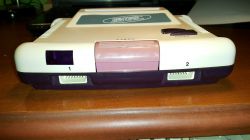
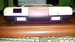
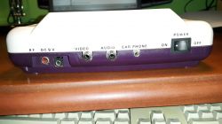
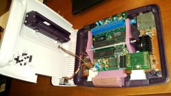
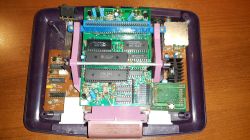
I become owner of quite weird but compact famiclone console:
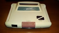
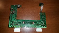
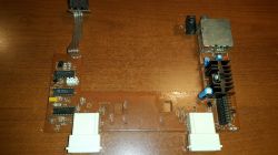
Image Image Image Image Image Image Image Image

The mainboard contains just ordinary set of chips (UA6527+UA6538+2x74368 + 74373 + 74139).

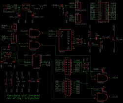
The add-on board with pad sockets is equipped with IRDA receiver (I've never heard of any consoles with infrared pads before) and some chips (7408, 4094, UA6581). Here is schematics of that board:
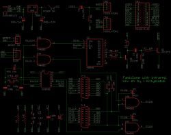
Image

If we consider standard 15-pin pinout for most famiclones (1=GND, 8=DATA, 9=CLK, 12=STROBE, 15=+5V), then:
* Socket marked as "1" is de-facto ready for PAD2 (with the exception that P2.D0 is ANDed with some signal from mysterious UA6581)
* Socket marked as "2" is non-functional

But when assuming that: 1=GND, 2=DATA, 12=STROBE, 14=CLK, 15=+5V) then this custom pinout might agree that 1=PAD1, 2=PAD2.

There are two jumper-wires (not soldered) which probably should be soldered when no irda & extra chips were soldered in.

What's the IRDA protocol & how UM6581 works is still not known. Some other famiclone's pads (IQ502) were equipped with UM6582.
Also, 4094 can reset console (and it does it quite often as sometimes this famiclone spuriously resets).
Re: Weird famiclone with infrared controllers
by on (#211508)
Ok, I did some measurements and research. Here are results:

UM6581 - details of operation
1. Package & pinout: DIP14, 300mils

Code:
         ,---V---.
!RESET?  |01   14|->VCC
 delay?  |02   13|->P2 inactivity pulse?
  XTAL1->|03   12|->P1 inactivity pulse?
  XTAL2->|04   11|->P2.D0
 P1.CLK->|05   10|<-P2.CLK
  P1.D0<-|06   09|<-STROBE
    GND -|07   08|<-IRDA
         `-------`


There is how the chip was connected in famiclone:
Image

2. Clock
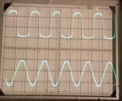
XTAL1 & XTAL2 are ceramic oscillator inputs (455 kHz). The chip has built-in clock generator (probably with inverter). During operation, there is sine wave at XTAL1 and TTL square wave at XTAL2. This clock is used by chip to decode signal from IRDA input & measure idle time time.

Image

Code:
+-1MEG-+               
|      |
+-1.2k----to XTAL2
|      |
+-XTAL-+--to XTAL1
| 455k |
|      |
330p  330p
|      |
GND   GND


3. Infrared receiver
Output from infrared receiver should be connected to IRDA input. Originally, 3-pin 38 kHz SONY SBX1610-52 INFRA RED SERIAL TRANSMISSION ENCODER RECEIVER is used (455 kHz / 38 kHz ~= 12)
This chip has two 8 bit registers to store states of eight buttons for each player. When it detects proper waveform on IRDA input, it updates internal register with received button states.

for player1: 00[A][B][Select][Start][Up][Down][Left][Right]11000011
for player2: 00[A][B][Select][Start][Up][Down][Left][Right]00111100

Each bit takes 500 us time:
* GND on IRDA input = blinking of LED at 38 kHz = logical 0
* VCC on IRDA input = LED turned off = logical 1
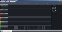
If no infrared signal is received within 25 ms for each player, internal button states for this player will be reset (set to ones).

Original infrared joypads probably send those signals only if any buttons are pressed, instead of continuous transmission, to save battery. If signals from two joypads are send at the same time, they will interfere and no valid data is received by the chip, so probably they send the data more often that once per frame (25 ms) or in diffrent intervals.

Image

4. Output
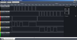
STROBE is connected to CPU's pin 39 and P1.CLK/P1.D0/P2.CLK/P2.D0 are connected to 74368 buffers in famiclone and they behave the same as for regular joypad:
* rising edge of strobe causes driving P1.D0/P2.D0 with state of A's button for 1/2 player,
* each rising edge of P1.CLK/P2.CLK causes the P1.D0/P2.D0 to be driven with state of next button (B/Select/STart/Up/Down/Left/Right),
* after eight edges, D0 is driven with 0.

Image

5. Miscellaneous
* Pin 1 & pin 2 have internal pull-ups to VCC and they acts as some kind of inputs, while pin 13 & pin 14 are outputs.

* Pin 1 is probably !RESET. If GND is applied, chip does not generate signals on pin 12/13, ignores IRDA input,returns 0xFF for pad1/pad2 and if there were time shift between pulses on pin 13 and pin 12, they will be in sync after releasing reset.

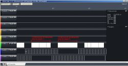
* There are pulses on pin 12 if no data is received for P1 within some time (and the same on pin 13 for P2). Those pulses have constant duty cycle of 12.5% and frequency, which can be set (lets call it fpoll)
If data for pads are received, there won't be any pulses. Maybe this signal can be used as some kind of notification for the pad to send signal.
Image

* Pin 2 selects fpoll (the maximum delay between receiving two signals for one pad which will not cause reseting button states.
**Driving with GND causes pin 12/pin13 to have 564 Hz
**Driving with VCC causes pin 12/pin13 to have 23.52 Hz
It is NOT analog input. Some kind of frequency signal could be put here, but it should be in phase with pin12/pin13.
Re: Weird famiclone with infrared controllers
by on (#211514)
krzysiobal wrote:
Originally, 3-pin 38 kHz SONY SBX1610-52 INFRA RED SERIAL TRANSMISSION ENCODER RECEIVER is used (455 kHz / 38 kHz ~= 12)
In my experience, infrared demodulator chips don't usually use a high-quality time source like the 455kHz resonator, instead just setting the demodulation frequency via an RC or LC.

Quote:
Each bit takes 500 us time:
2kbit/sec is surprisingly fast for modulated IR. Most of the remotes in the LIRC database seem to use bit rates closer to 500-1000 bits/sec. They also usually encode clock and data in the same stream, rather than start bits...

Actual IrDA doesn't use 38kHz modulation, in order to support higher bandwidths.
Re: Weird famiclone with infrared controllers
by on (#212084)
The UA6581 chip is used to decode the remote controller infrared signal and in the remote controller is UA6580 to encode and transmit signal.This remote controller can switch 1P/2P and when you press SELECT + A button ,the console will reset.Both of the chip are created and manufactured by UMC(联华半导体公司) corp.
Attachment:
IMG20161208131159.jpg
IMG20161208131159.jpg [ 1.68 MiB | Viewed 3215 times ]
Re: Weird famiclone with infrared controllers
by on (#212087)
Thank you! Can I ask for photo of gamepad's PCB from top side?
Re: Weird famiclone with infrared controllers
by on (#212116)
Attachment:
QQ图片20180122102602.jpg
QQ图片20180122102602.jpg [ 1.28 MiB | Viewed 3166 times ]

Attachment:
QQ图片20180122102545.jpg
QQ图片20180122102545.jpg [ 1.32 MiB | Viewed 3166 times ]

Attachment:
IMG_20160706_093802.jpg
IMG_20160706_093802.jpg [ 2.24 MiB | Viewed 3166 times ]

Attachment:
IMG_20160706_093742.jpg
IMG_20160706_093742.jpg [ 2.68 MiB | Viewed 3166 times ]

This model of famiclone console(SY-200) were designed in 1989,which was popular in China and been exported to Brazil and some European countries. Two remote controller can not control 1P and 2P in the same time , the console can only decode one of the infrared signals. I guess this model of wireless controller chip (UA6581 UA6580) can be replaced by MCS-51.
Re: Weird famiclone with infrared controllers
by on (#212117)
Is there a UA8580, a successor to UA6581 that offers a cleaner decoded signal and better power use? :P

(Looks like UMC had no qualms about reusing MOS part numbers for unrelated ICs.)
Re: Weird famiclone with infrared controllers
by on (#212202)
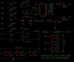
I reverse enginereed that pad, here is schematics & pinout for the chip.
The turbo generator is done using additional 3 inverters.

Code:
UM6580 - wireless padd transmitter
         ,---V---.
     VCC-|01   18|->!LED                     
         |02   17|<-RIGHT
         |03   16|<-LEFT
!P1!/P2->|04   15|<-DOWN
  XTAL1->|05   14|<-UP
  XTAL2->|06   13|<-START
         |07   12|<-SELECT
   IRDA<-|08   11|<-A
     GND-|09   10|<-B
         `-------`


Image Image Image
Re: Weird famiclone with infrared controllers
by on (#212354)
Attachment:
IMG_20180126_211643.jpg
IMG_20180126_211643.jpg [ 1.2 MiB | Viewed 3041 times ]

Attachment:
IMG_20180126_211454.jpg
IMG_20180126_211454.jpg [ 1 MiB | Viewed 3041 times ]

Attachment:
IMG_20180126_211742.jpg
IMG_20180126_211742.jpg [ 1.02 MiB | Viewed 3041 times ]
Re: Weird famiclone with infrared controllers
by on (#212769)
I have bought five transimitter chip (UA6580) from Taobao and here is the link https://item.taobao.com/item.htm?spm=a2 ... t=6#detail
I am trying to draw PCB that can put into the clone NES control pad and I guess this chip support wide voltage. I will use the 3.7V Li-Polm battery as the power supply. If this subject success, I will upload the PCB source document to our website. Hope everything goes well :D
Attachment:
IMG_20180131_190532.jpg
IMG_20180131_190532.jpg [ 1.58 MiB | Viewed 2960 times ]