SNES - RAM + battery backup

This is an archive of a topic from NESdev BBS, taken in mid-October 2019 before a server upgrade.
View original topic
SNES - RAM + battery backup
by on (#220236)
I want to discuss best way for RAM battery backup in SNES cartridges (without using specialised chips or MAD1).

From those of SNES cartridges with battery that has I have examined, they:
* Use MAD chip to protect WRAM
or
* Use transistor circuit to control positive chip enable line
Image

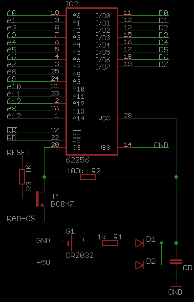
I want to make programmable cartridge but I have only 62256 memories (with one, negative chip enable line).
I created circuit like shown below. I put R3=100k but then for example Final Fanasy VI hangs after title movie.

So I changed R3 to 1k and it seems to work, but is that proper way? Should also VCC be taked into account so when it drops below certain level, /CE goes high?
Image
Re: SNES - RAM + battery backup
by on (#220237)
RacerMate Challenge uses the "PNP transistor as voltage threshold detector" with some random 74HC logic to combine +CE into /CE.

There's a circuit I've seen bouncing around the forum involving a common-base amplifier to combine the two signals, also.
Re: SNES - RAM + battery backup
by on (#242637)
Hey, have you tested this further? It looks like it'll work to me, and it might even solve my leakage problem I'm having with the SRAM signal from my decoder.

Though there still could be some leakage through the transistor depending on the part...
Re: SNES - RAM + battery backup
by on (#242640)
I can confirm 6264 circuit works perfect (since that's what's bascically in a 1A3B cartridge).

Haven't tested 62256 yet but can't one just use /CE on 6264 instead of CE2 and have just one circuit for all type of SRAMs?

CE2 of 6264 could be tied to VCC instead.
Re: SNES - RAM + battery backup
by on (#242643)
Ice Man wrote:
I can confirm 6264 circuit works perfect (since that's what's bascically in a 1A3B cartridge).

Haven't tested 62256 yet but can't one just use /CE on 6264 instead of CE2 and have just one circuit for all type of SRAMs?

CE2 of 6264 could be tied to VCC instead.


The problem arises when the /CE pin is pulled up to VCC while also tied to a 139 decoder output. When the decoder is unpowered and an output pin is still connected, there will be a leakage current through the output to GND. This drains the battery faster, and puts the SRAM into a higher leakage state too since /CE isn't pulled high enough. It's ok on the CE2 pin of a 6264 because that pulls down to ground, so the leakage on the decoder doesn't matter.

I've got a more detailed analysis on this post
Re: SNES - RAM + battery backup
by on (#242646)
The NOT(A>B) BJT can be used like:

Code:
                 V_UPS
                   |
                   R
                   |
                   +----- /CE_OUT
                  /
POWERGOOD---R---|<  V_UPS
                  ↘  |
                   + R
                   | |
        /CE_IN ----+-+


I know I've seen this schematic as applied to battery de-selection before, but I can't find it right now.
(edit) obviously it's present in krzysiobal's post at the beginning here, but I'm thinking I saw it in a post from much longer ago.
Re: SNES - RAM + battery backup
by on (#242647)
lidnariq wrote:
The NOT(A>B) BJT can be used like:

Code:
                 V_UPS
                   |
                   R
                   |
                   +----- /CE_OUT
                  /
POWERGOOD---R---|<  V_UPS
                  ↘  |
                   + R
                   | |
        /CE_IN ----+-+


I know I've seen this schematic as applied to battery de-selection before, but I can't find it right now.


The logic seems to work out for normal operation. V_UPS is the SRAM VCC (so 5V or 3.3V). POWERGOOD is /RESET from the cartridge connector. /CE_IN comes from the decoder, /CE_OUT goes to the SRAM. When power is on, and /RESET is high, /CE_OUT follows /CE_IN. When /RESET is low, /CE_OUT is clamped to VCC.

The only question then is what happens when the power is off (and the cartridge is removed from the socket). V_UPS goes to 3.3V, /RESET is floating (a high enough base resistance should be able to mitigate the noise effects, I think), but /CE_IN is still tied to the decoder, which has a leakage current. So if it's not going to leak through the transistor, it's just going to leak through the resistor tied to /CE_IN and to V_UPS, right? Maybe it'd force /CE_OUT to a high enough voltage to keep the SRAM in low-leakage state, but I think it's still going to drain the battery.
Re: SNES - RAM + battery backup
by on (#242649)
poorstudenthobbyist wrote:
it's just going to leak through the resistor tied to /CE_IN and to V_UPS, right?
[...]
but I think it's still going to drain the battery.
Yes, there'll still be some static dissipation there. But it might be possible for the pull-up resistor to be large enough to make it unimportant. Not certain. It's definitely the sort of thing that needs some experimental measurement on real parts.

Quote:
Maybe it'd force /CE_OUT to a high enough voltage to keep the SRAM in low-leakage state
This part is assured. No current flowing from POWERGOOD to CE_IN, no current flowing from CE_OUT to CE_IN.
Re: SNES - RAM + battery backup
by on (#242650)
So, I tried this circuit (in the OP) with the HM62256 and I see a 0.2V drop from the battery to the SRAM. I read a 0.13V drop on the diode (D1), so one would expect a 0.07V drop across the resistor, but I don't read that with my meter. I don't know why, or where else the voltage could be accounted for. The /CE pin is the same voltage as the SRAM VCC, so it meets the low leakage criteria. I ordered some of the low power versions of the 256K SRAM so we'll see how that goes when I get them in.

The 64K GoldStar SNES SRAM measures a 0.2V drop to the VCC of the SRAM as well, however the entire 0.2V drop seems to be completely across the diode instead of somewhat across the resistor (at least it's "completely" across the diode within 10mV precision, as that's what my voltmeter goes down to). This one doesn't have a mysterious disappearance of 0.07V.

I also tested the NPN circuit the SNES boards use (with my custom boards) and I still read the 0.2V drop across the diode. But, when I check an official Nintendo board, I see less than 0.1V drop. Maybe their diodes have better forward voltage drop? Not sure. I guess I could try swapping the diodes.

In either case, 0.2V on the 1N914 datasheet doesn't even show up on the Vf vs If curve. So.... really low leakage current?

Image
Re: SNES - RAM + battery backup
by on (#242652)
I'd be comfortable calling that ≈1µA.
Re: SNES - RAM + battery backup
by on (#242656)
So I tried taking a diode out of an official SNES board and putting it in where D1 goes to see if there's still a 0.2V drop on my board. I do still read a voltage drop with this diode. Ok, so I figured it was something else in the circuit, even though there's not much else it could be. When I went to put the original diode back in the SNES board, I lost it. So I put a 1N914 in instead, and now I'm reading a 0.2V drop on the official SNES board. So I'm all mixed up.

Does anyone else have a genuine SNES board lying around with this NPN circuit? Just to see if you can read a 0.2V drop across D1. Measure the VCC on the SRAM too (pin 28 to pin 14). I don't actually seem to have another game like this, all my other games have MAD-1 chips in them haha
Re: SNES - RAM + battery backup
by on (#242662)
On my 1A3B-12 copy of LoZ:aLttP, Vbat = 3.295 ; VD2 = 84mV, VR1 = 0 (less than my ability to measure)
On my 2A3B-01 copy of SMAS, Vbat=3.086 ; VD2 = 214mV, VR1 = 0.2mV (i.e. 0.2µA)
Re: SNES - RAM + battery backup
by on (#242665)
Thanks a lot for checking that.

Not sure why sometimes the drop is 0.2V, sometimes it's less, but if other SNES boards show this characteristic I guess I shouldn't worry about it.
Re: SNES - RAM + battery backup
by on (#242666)
Remember that a diode has an exponential relation between forward voltage and current - the ideal diode (without the parasitic resistance or reverse voltage regions) has a relation of

current through diode = "scale" current · (exp(voltage across diode · charge of electron ÷ Boltzmann constant ÷ temperature) - 1)

or equivalently,

voltage across diode ∝ log(current through diode)

so seeing 0.2V is perfectly fine for low currents. Seeing even less voltage just implies that much less current.

This logarithmic relation can be used to make analog computers, such as the log amplifier (which can then be used to do multiplication in analog)
Re: SNES - RAM + battery backup
by on (#242677)
I guess I was just worried that the SHVC-1A3B board I had showed <0.1V drop but when transplanting all the parts over to my board with the equivalent circuit, it became an 0.2V drop. But you're right, I should look more at what's actually happening.

I just get nervous when I have to change something on my boards and get them made, because there have been other times where I was too hasty and I ended up wasting like $20 to $30 :\
Re: SNES - RAM + battery backup
by on (#242679)
Ok, I'm starting to think my voltmeter isn't reliable... on OP's circuit I'm reading anywhere between 2.5V and 3.0V on the SRAM VCC, and also different voltages on the resistor. When I connect it to my oscilloscope instead VCC is a steady 3.0V. I don't know what's happening, might be time to get a better meter.

I think my plan going forward is making a board with some selector pads, one for the known 64K circuit, one for this new 256K circuit, then leave some boards plugged in for a while and see if they last.
Re: SNES - RAM + battery backup
by on (#242698)
poorstudenthobbyist wrote:
Ok, I'm starting to think my voltmeter isn't reliable... on OP's circuit I'm reading anywhere between 2.5V and 3.0V on the SRAM VCC, and also different voltages on the resistor. When I connect it to my oscilloscope instead VCC is a steady 3.0V. I don't know what's happening, might be time to get a better meter.

I think my plan going forward is making a board with some selector pads, one for the known 64K circuit, one for this new 256K circuit, then leave some boards plugged in for a while and see if they last.

Check the battery in your meter, also clean the battery terminals. Put the meter in ohms mode and connect the probes together, wiggle them all around, make sure ohms stays very close to 0. If not, it can be bad or dirty probes.