What's goin on with the Casel Zapper?

This is an archive of a topic from NESdev BBS, taken in mid-October 2019 before a server upgrade.
View original topic
What's goin on with the Casel Zapper?
by on (#234841)
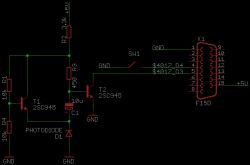
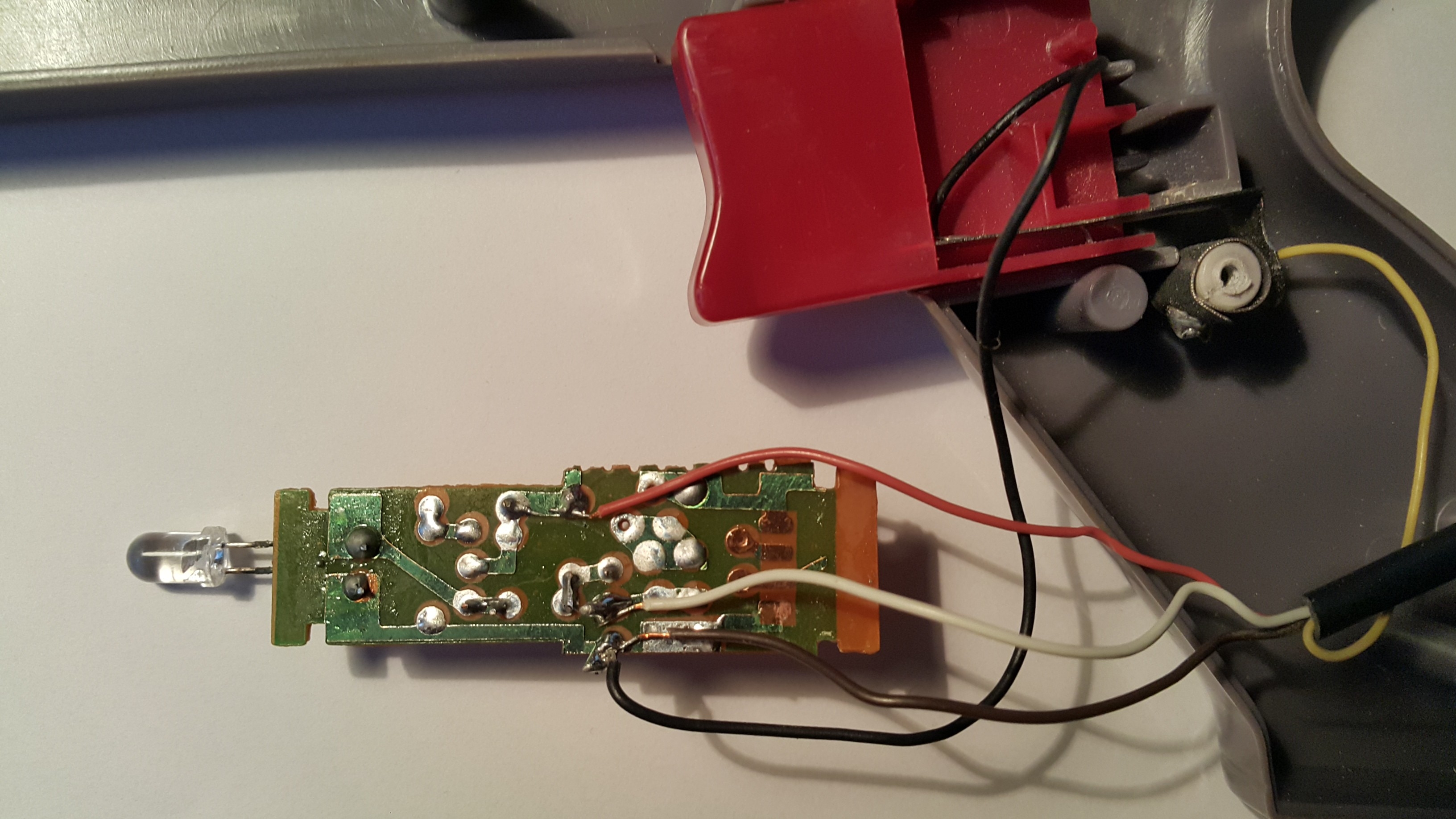
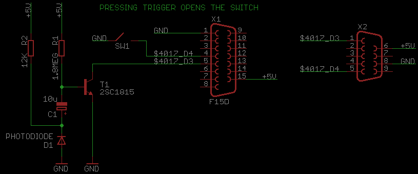
When you look into regular famiclone zapper, you might encounter classic 1 transistor solution with values like:
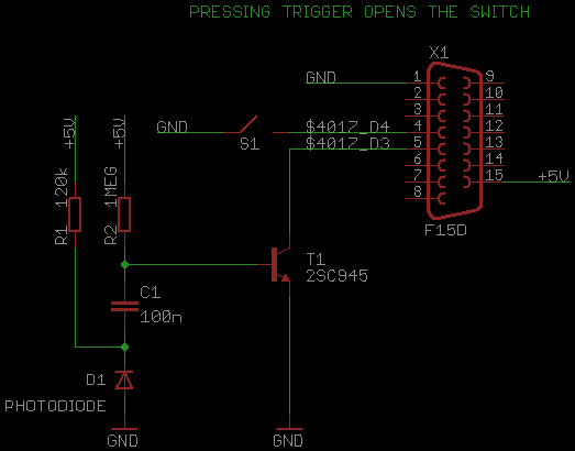
Image Image Image

or:
Image Image Image

If you're more lucky, there might be 2 transistors:
Image Image Image

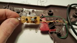
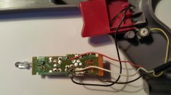
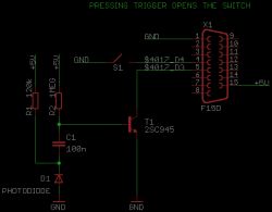
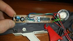
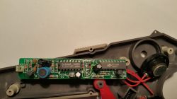
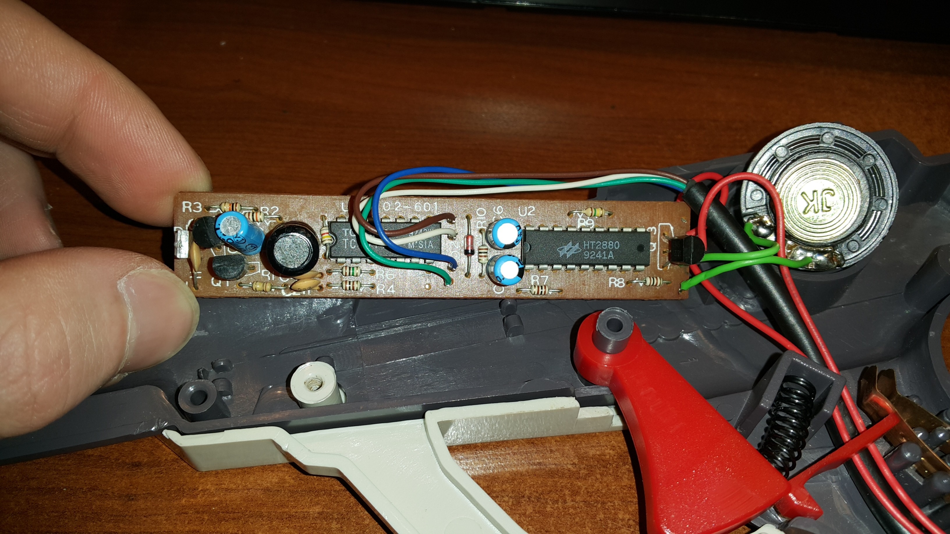
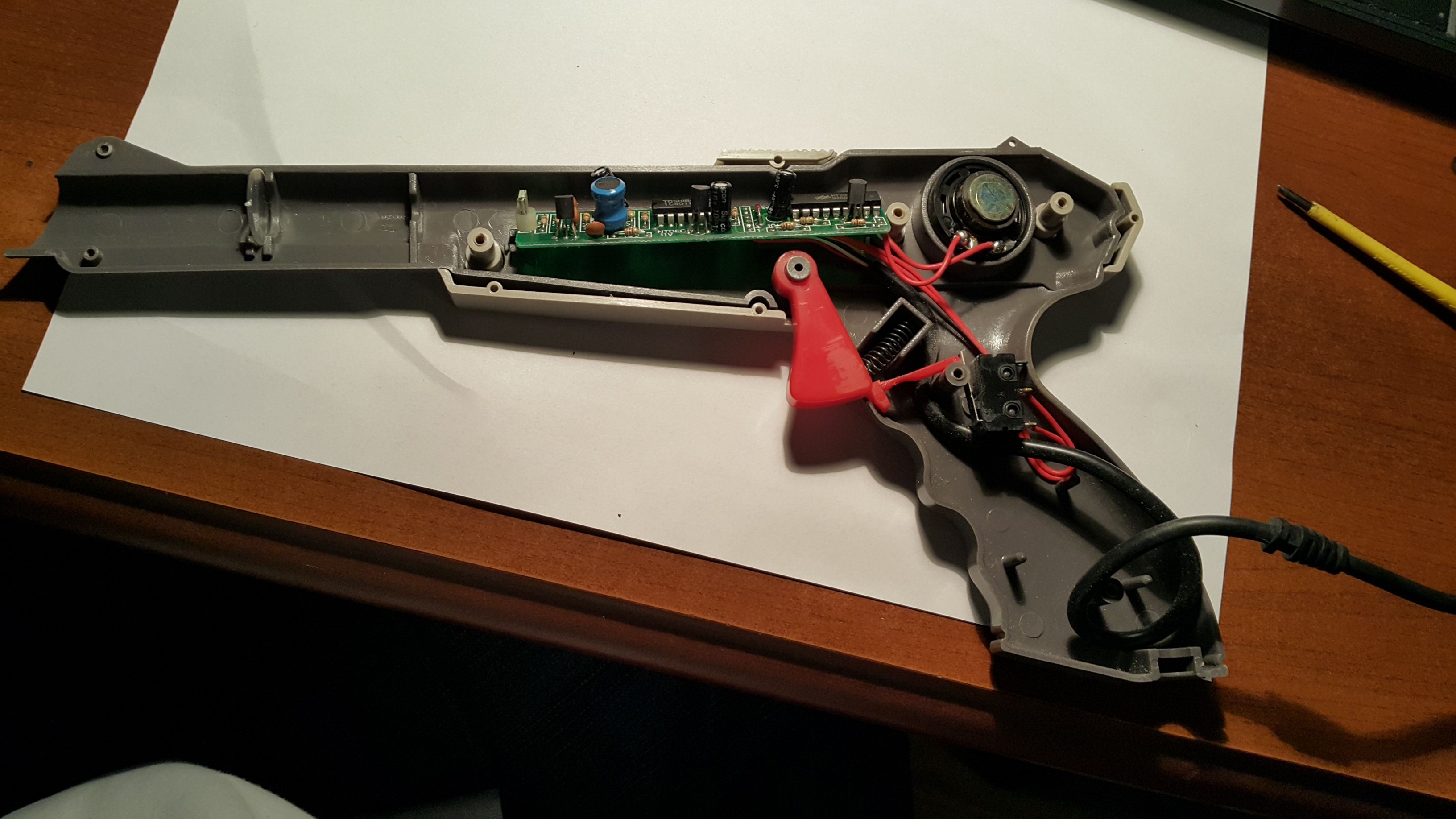
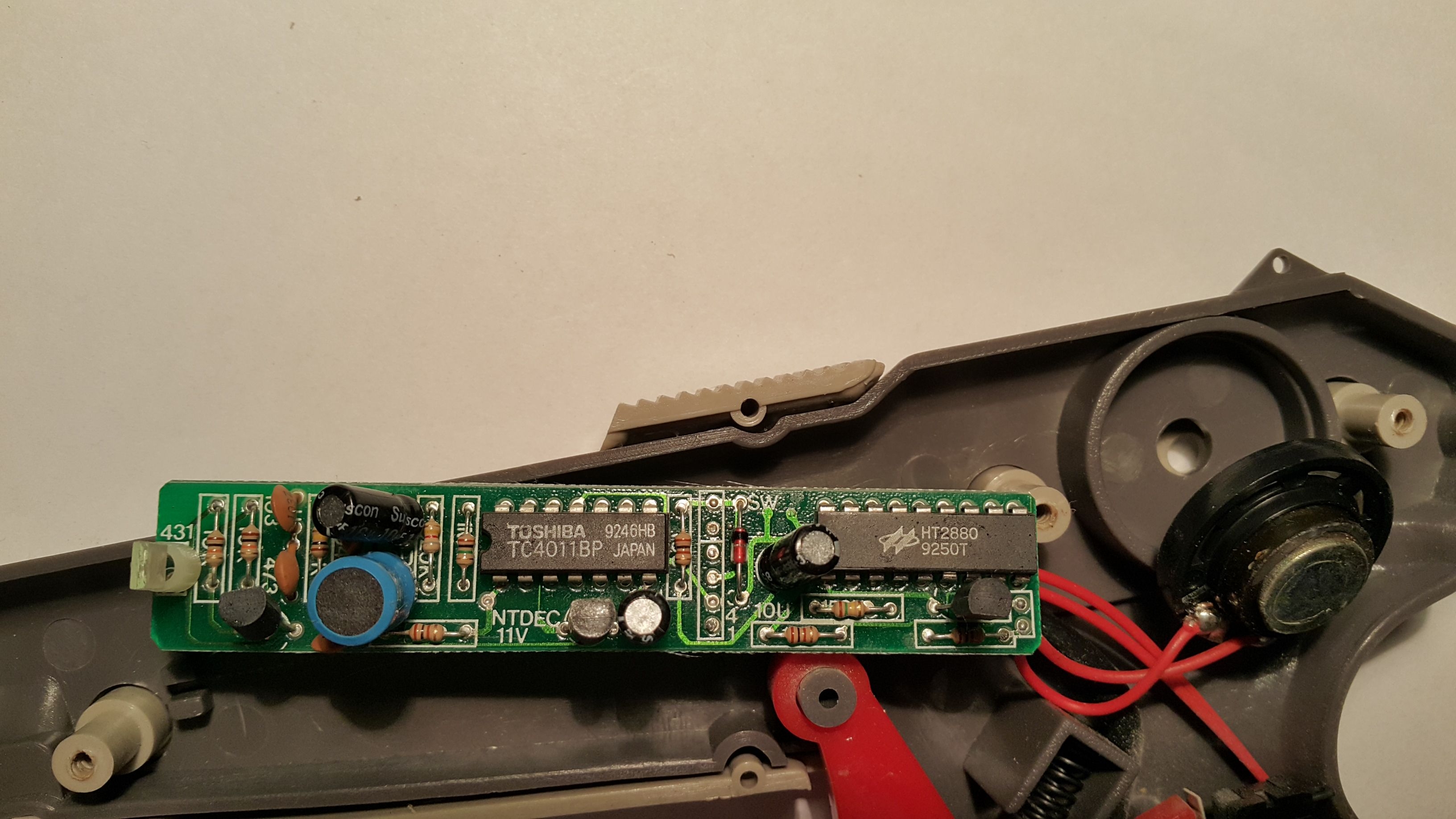
But the Casel zapper (which uses additional chip HT2880 chip for riffle sound playback) has much more complicated photodiode sensing circuit:
Image Image Image

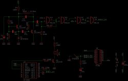
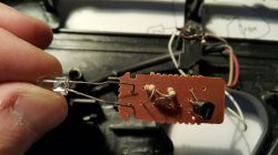
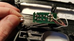
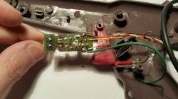
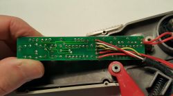
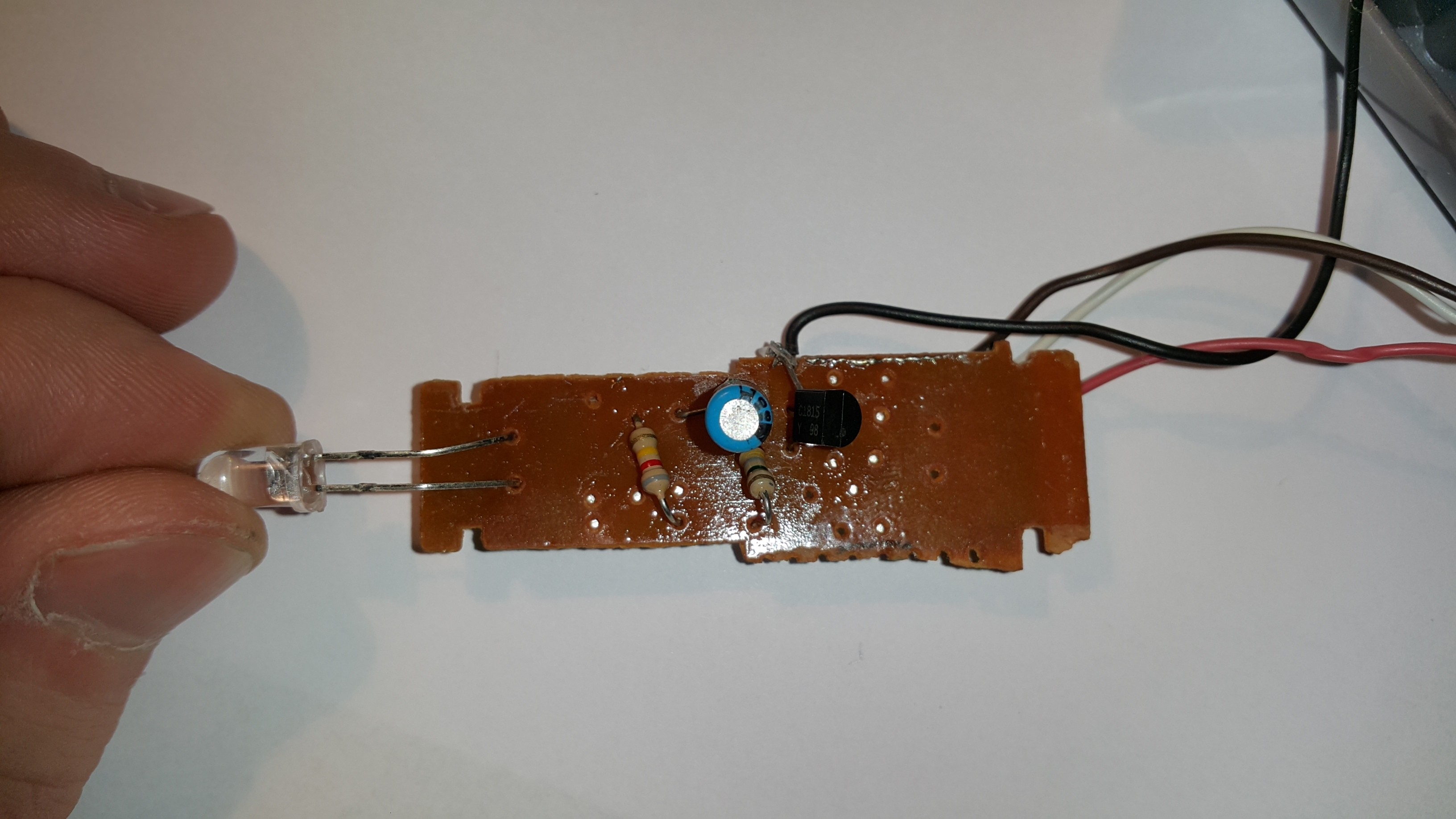
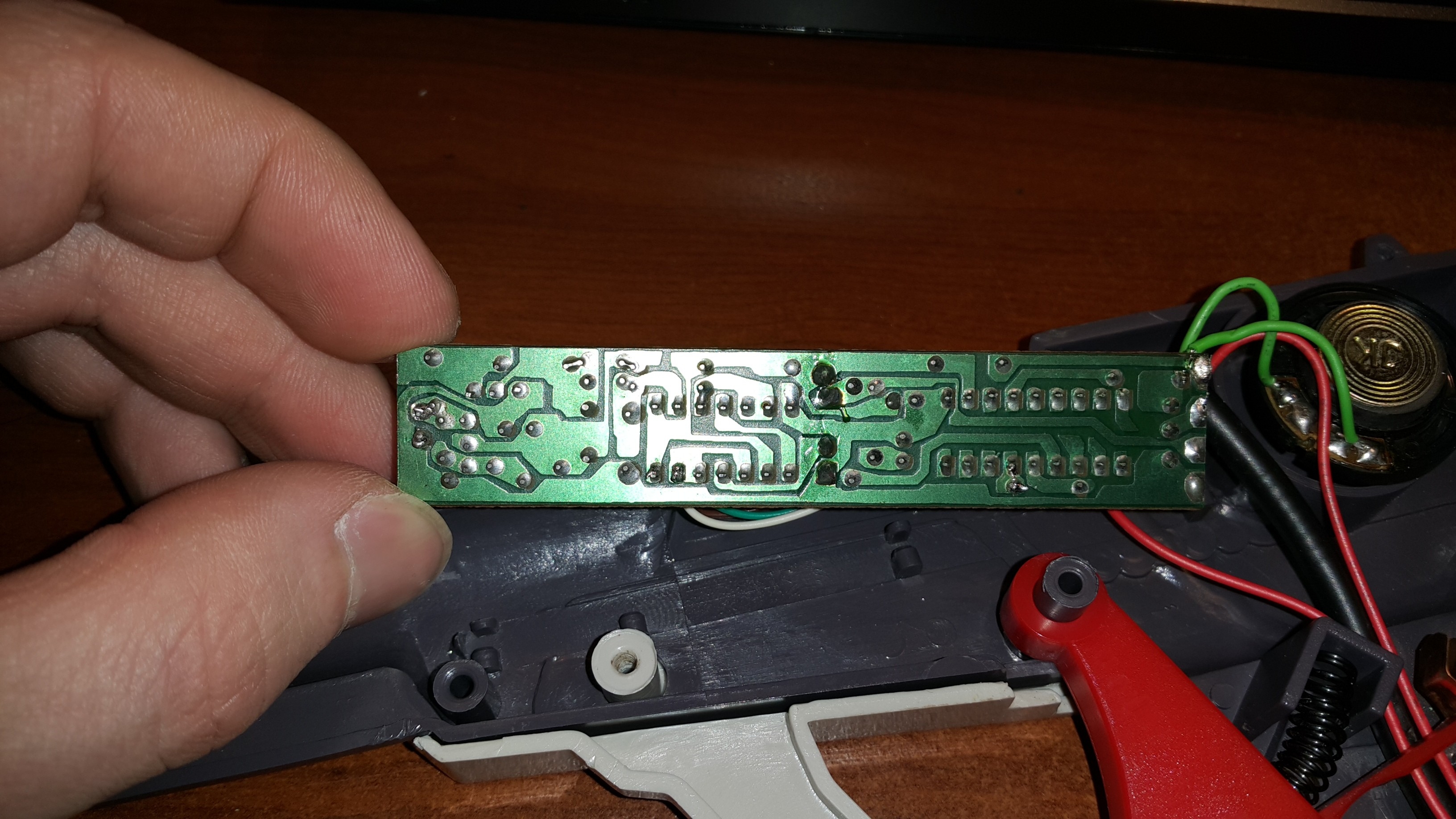
Here is another revision:
Image Image Image

Any idea how this circuit works?

--
Re: What's goin on with the Casel Zapper?
by on (#234900)
It seems like T2 must be wrong in your 2-transistor schematic. I think that the base and collector need to be swapped.
Re: What's goin on with the Casel Zapper?
by on (#234910)
About the Casel circuit...

The NAND gates, especially the last two, are looking as if the circuit was made by somebody who enjoys domino races. Unless there was some real purpose... The gates might make sense for adjusting the horizontal position/timings (if the same circuit were used on a console that can measure the horizontal position). Or the gates could useful to implement crossed wires on a single-layer PCB (but that doesn't seem to be the case here).

The inductor coil, hmmm, it might be useful to prevent sharp current transitions, or it might make the current to be kept flowing after the transistor is switched off... possibly ending up with more than 5V to be getting pumped to somewhere?
The other thing is that almost all signals are passed through capacitors, so there would be only short signals, no continous ones.

Well, I don't understand what the circuit is doing. Some guesses: It might be something that can sense Darker-to-Brighter transitions (as opposed to Black-to-White). Or it might be somehow optimized for 15kHz signals. Or parts of it might be intended to avoid issues about the power supply being shared with the built-in sound circuit.

Does that circuit work better than the other ones? Like feeling more reliable in general, or working undisturbed of daylight, or working with games that use non-white images? You could also do scope checks on the signal output and compare it with the other circuits.
Re: What's goin on with the Casel Zapper?
by on (#234912)
I used to work with a guy that would have loved to help figure out how it works. I did my best to simulate your circuit with LTSpice, but I have no idea if this is actually working right. I approximated the light sensor with a 10mV 15kHz square wave with series 1k resistor, not sure how realistic that is.

Attachment:
zapper_sim_1.png
zapper_sim_1.png [ 61.66 KiB | Viewed 6838 times ]


Attachment:
zapper_sim_2.png
zapper_sim_2.png [ 72.83 KiB | Viewed 6838 times ]


Attachment:
zapper_sim_files.zip [47.72 KiB]
Downloaded 182 times


Actually, I did not place a GND symbol in this schematic, I think that would be a problem for the simulation.
Re: What's goin on with the Casel Zapper?
by on (#234913)
The input doesn't look right, I would expect a sharper high to low (or low to high?) transition when the light goes on, and a softer transition when it goes off, due to afterglow. If the afterglow lasts to next scanline then it might also sum up. And the lens might receive more light in the middle scanline. And the speaker might produce some unpredictable wobbling on the power supply, depending on its volume, in worst case that might even cause the video output voltage of the console to wobble, too.
Anyways, the simulation output suggests that the output toggles at the begin of transitions, maybe other circuits would toggle only when the input is reaching the max voltage?
Re: What's goin on with the Casel Zapper?
by on (#234921)
I would not trust my simulation very much at this point. I added a GND reference, and the output no longer did anything. I think I am kind of stuck now. LTSpice is a free program, if you or anyone would like to try playing with this. I included the CD4000 library in the zip file, which came from here: https://groups.yahoo.com/neo/groups/LTspice/info
Re: What's goin on with the Casel Zapper?
by on (#235824)
- The photosensor here is in "photocurrent" (reverse-biased if it's a photodiode) mode, not photovoltage. Use a current source in LTspice instead of a voltage source. (Also, turn on "active load")
- even if a photodiode is in photovoltage mode (forward-biased), the output impedance is very variable.

( Photocurrent mode is higher bandwidth and gain, but requires more complex support circuitry )

- The chain of NAND gates here is being used to square up the output, increasing very marginal voltage differences up to full CMOS rail-to-rail. The first one (with R6) is also being used to move the signal to be in the middle of the NAND gate's high-gain inverting region.

- Did krzysiobal mean 61 millihenry or 61 microhenry for the inductor?

The big pile of analog before the inverters look like it's just trying to be a pulse extender: the photodiode should only conduct while it sees light, or a couple of microseconds. But it'd be a lot easier for the polling logic if it were true for ten to 60 microseconds.

For me, the sim extends a 4 us pulse into a 42 us pulse. I'd naively think it'd be better if it blurred scanline to scanline together, but ... I guess that's technically not necessary.
Re: What's goin on with the Casel Zapper?
by on (#236068)
Quote:
Did krzysiobal mean 61 millihenry or 61 microhenry for the inductor?

mili

I got another Zaper for fix. This one also uses additional sound chip, but it is much 'poorer' in design:
Image Image Image Image
They did not even bother to put resistor on transistor's base which controls speaker. Plus the trigger-switch, which is really is two metal plates touching each-other.

I wrote simple ROM that displays values read from $4016/$4017. This zapper, when pointed into constant light source (lamp), returns 0 (on D3) for about second and then it switches back to 1.

The ones with even larger cap (#1) returns to 1 after 5-10 seconds, while while the one with small ceramic cap (#2) makes just quick 0-1 pulse

There is also real mess with what triggers do - on half of Zappers, it opens switch when pressed and on the other half - it closes it.

--

I fixed the diodes in all schematics - in fact, it is always reverse-biased (the more light passes through it, the smaller is its dynamic resistance) ~~ no light = open, light = short