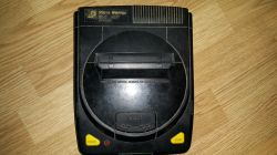
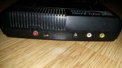
Few days ago I got two famiclones for fix - Micro Genius IQ 1000 and IQ 2000. Both of them works in NTSC mode (quite rare for a famiclones, which are mostly in Dendy-mode) and both of them have infrared receivers.
IQ 1000
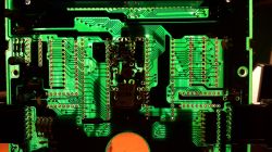
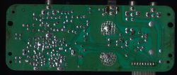
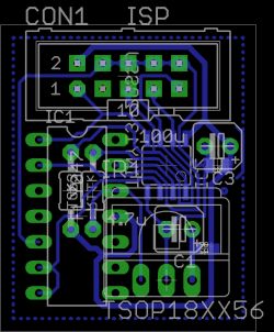
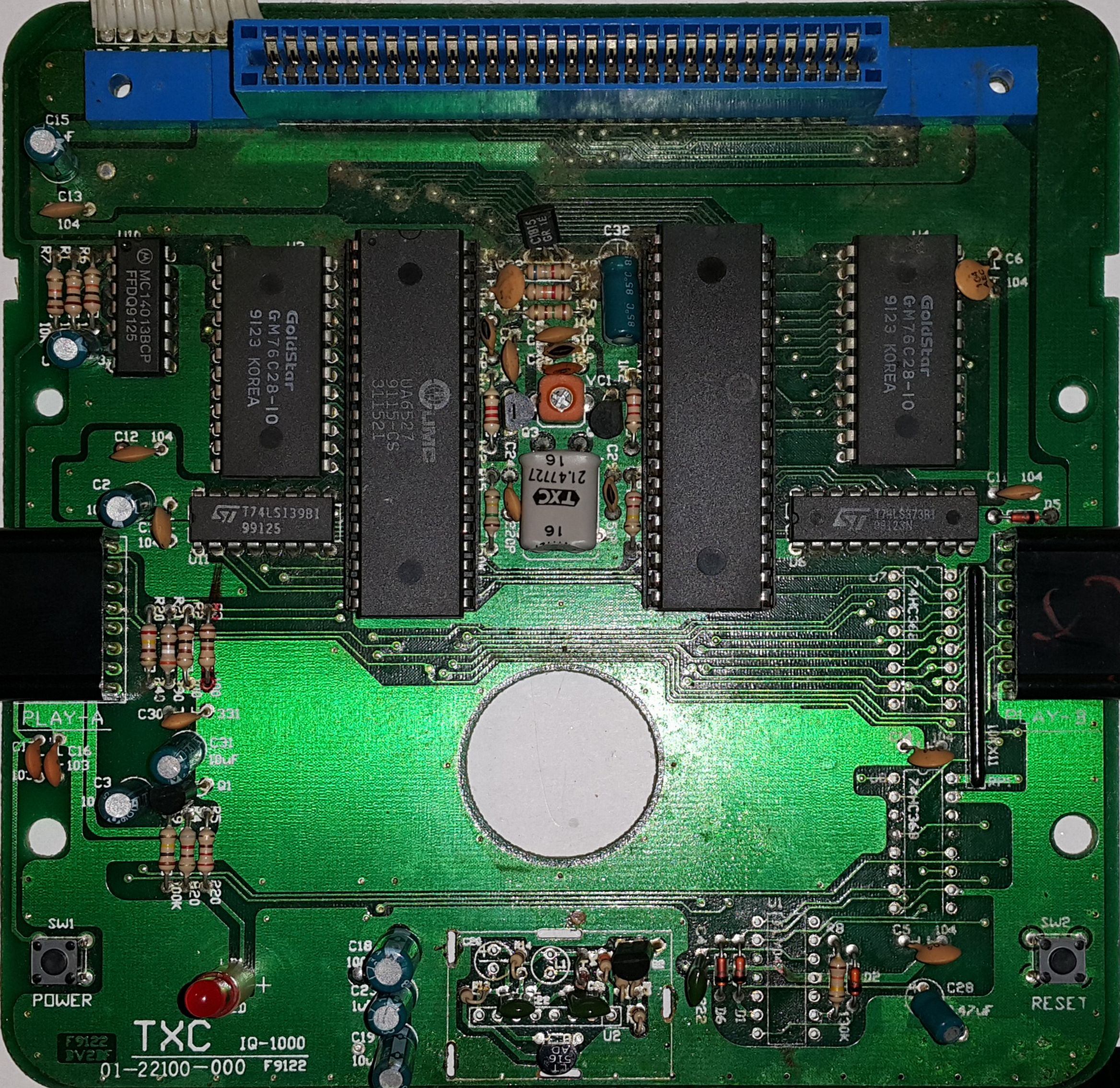
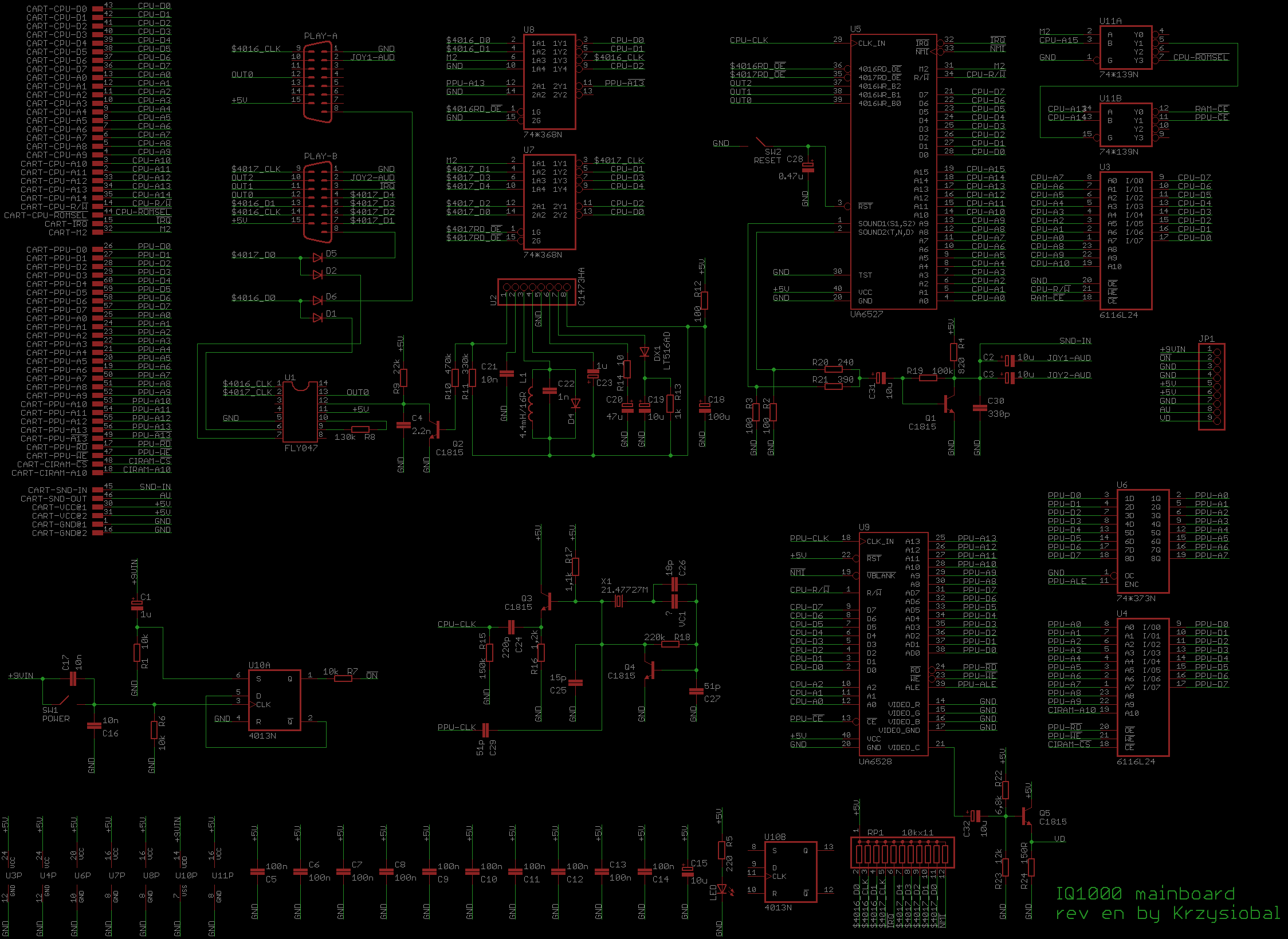
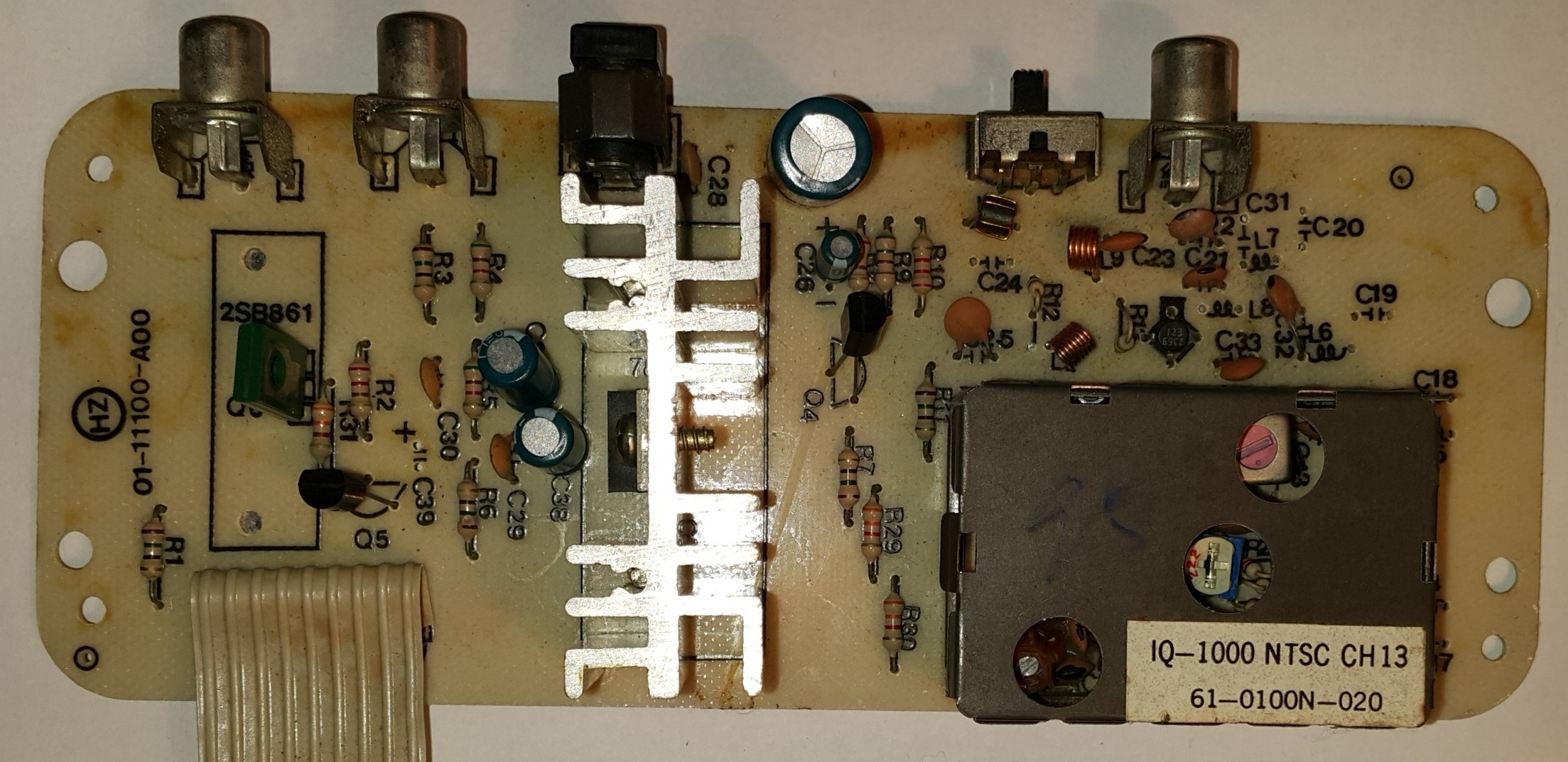
Chip version. Quite weird feature is the use of tact-switch, which clocks 4013 flip floop which controls transistor which passes the +9V, instead of the mechanical switch. The broken element was 4013 (powered directly from +9V), which is the first object that gets hurt when incorrect power supply is plugged.
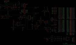
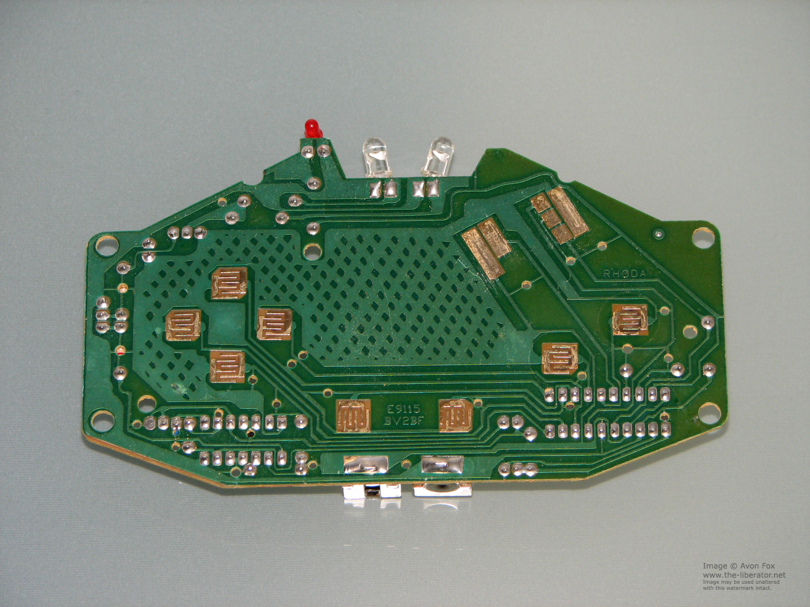
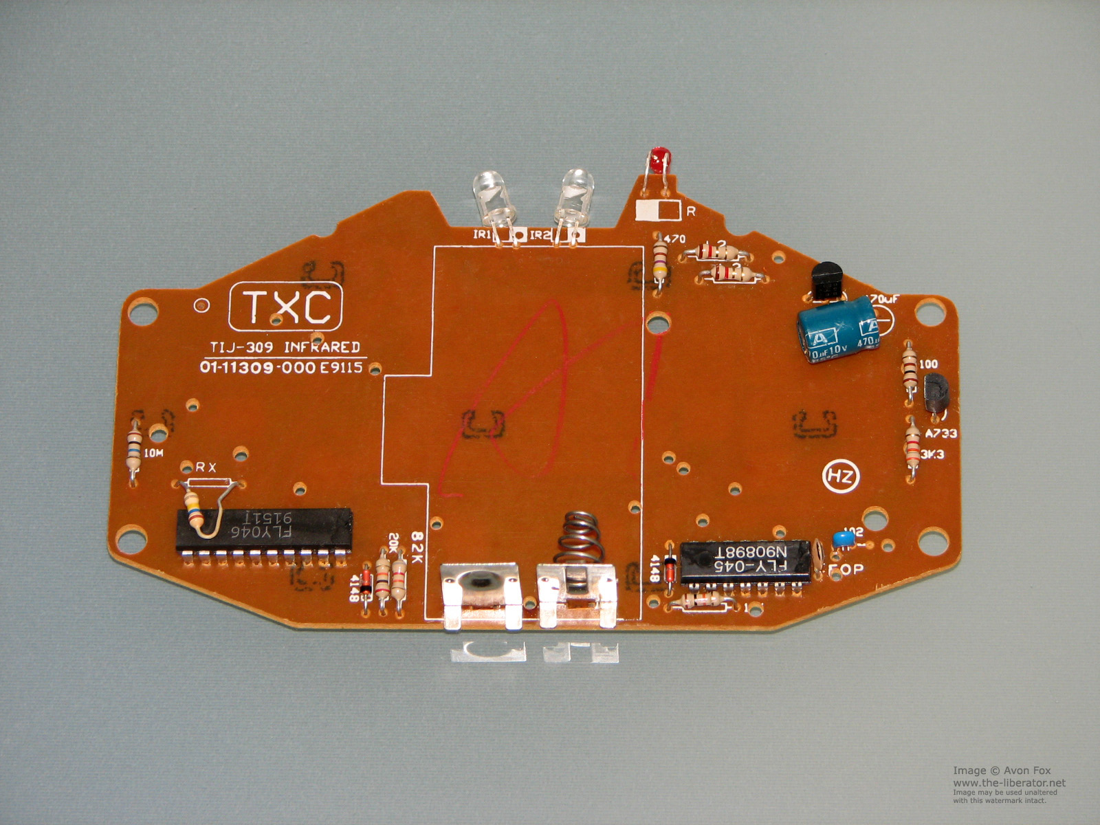
Instead of putting IR receiver (like the TSOP1838), they prefered ordinary photodiode, some mysterious C1473HA SIL8 chip and a lot of R/L/C/D components, enclosed in a Faraday's cage. Everything is connected to FLY047 chip, which receives the incoming serial joypad data and passes it to CPU.
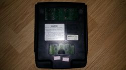

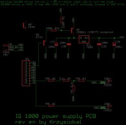
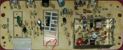
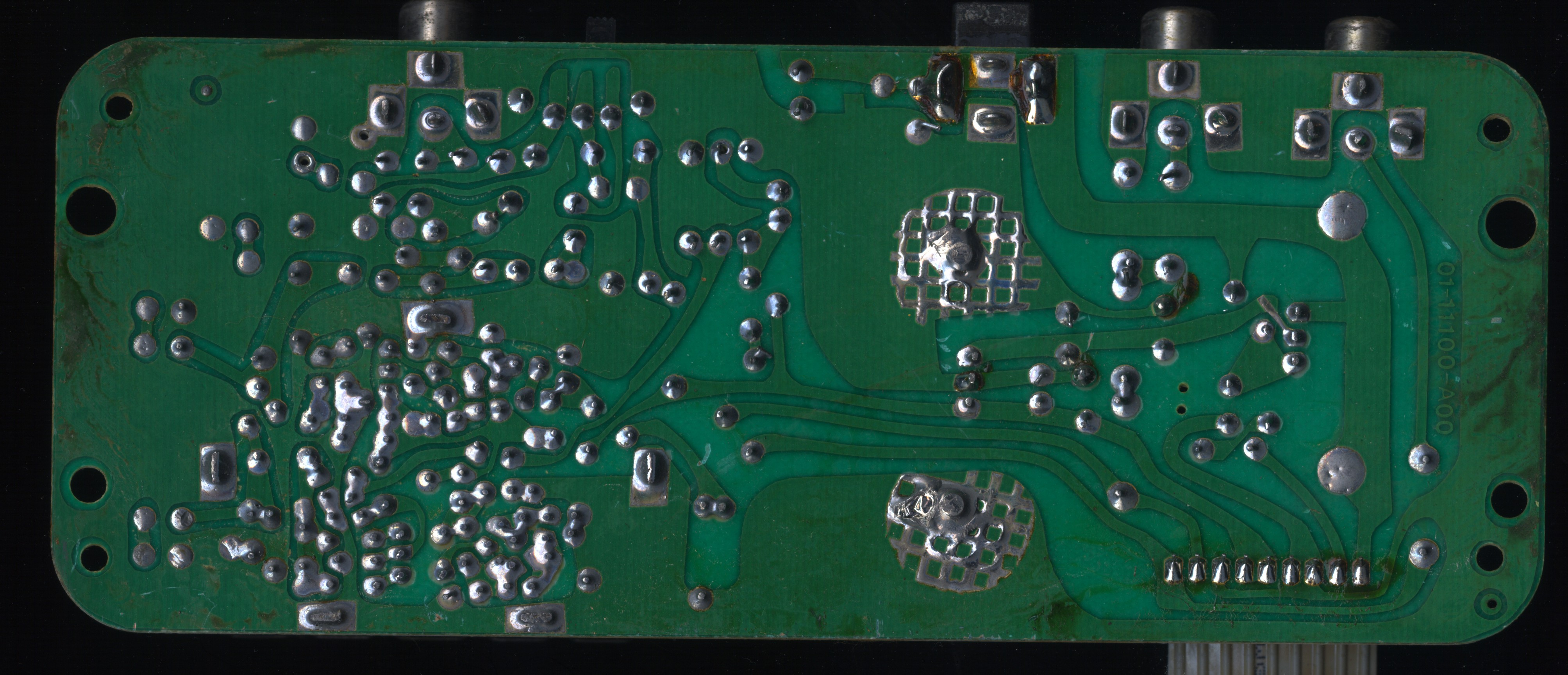
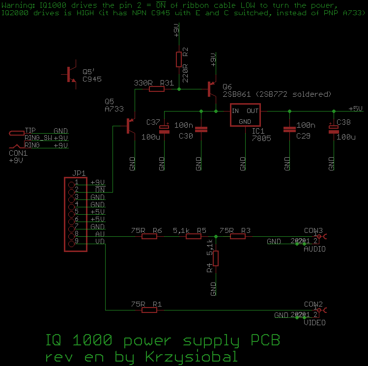
Here is the power supply PCB with transistors controlling the input voltage:
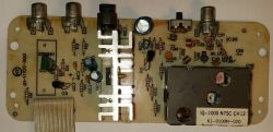
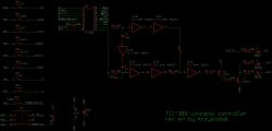
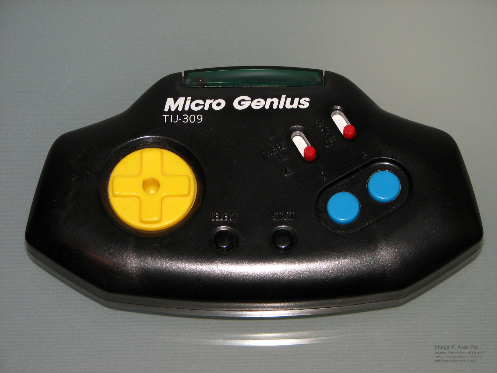
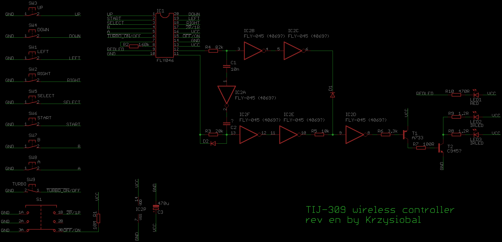
The console is designed to work with TIJ-309 wireless controller.

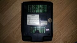
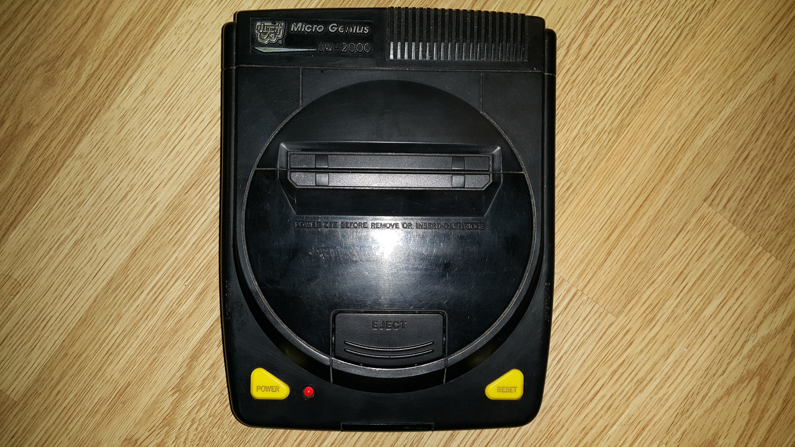
IQ 2000
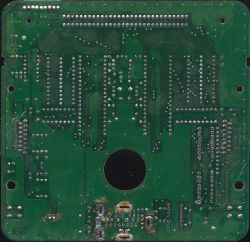
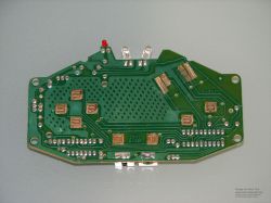
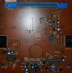
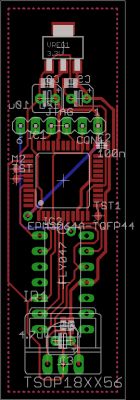
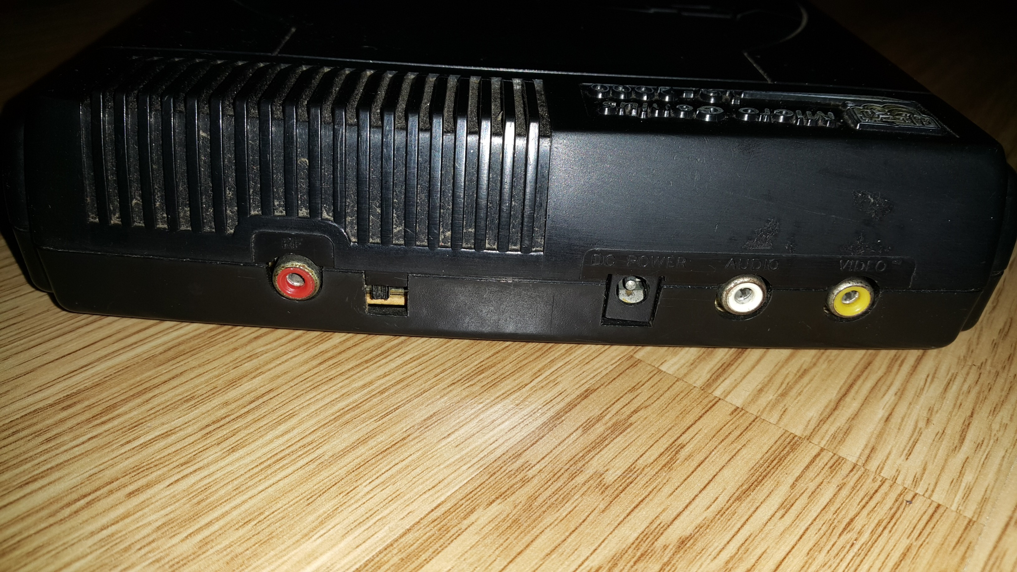
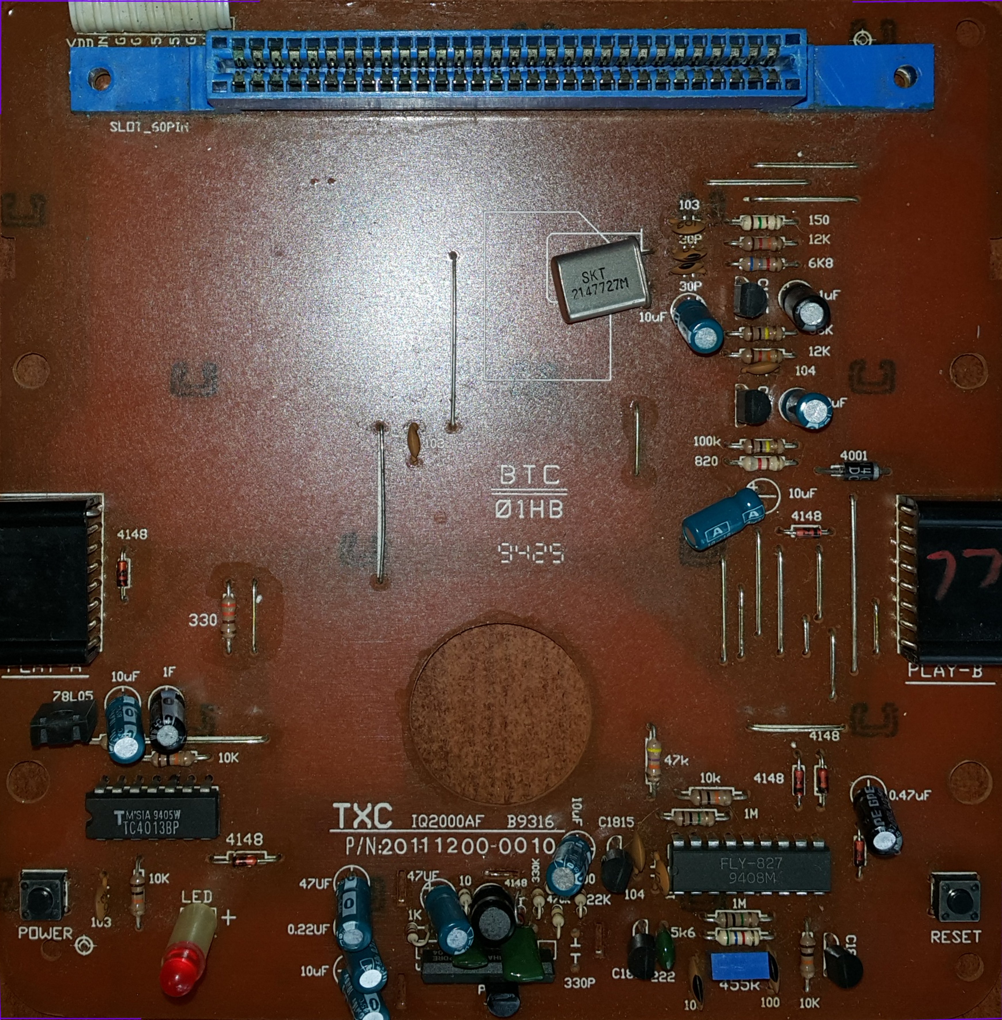
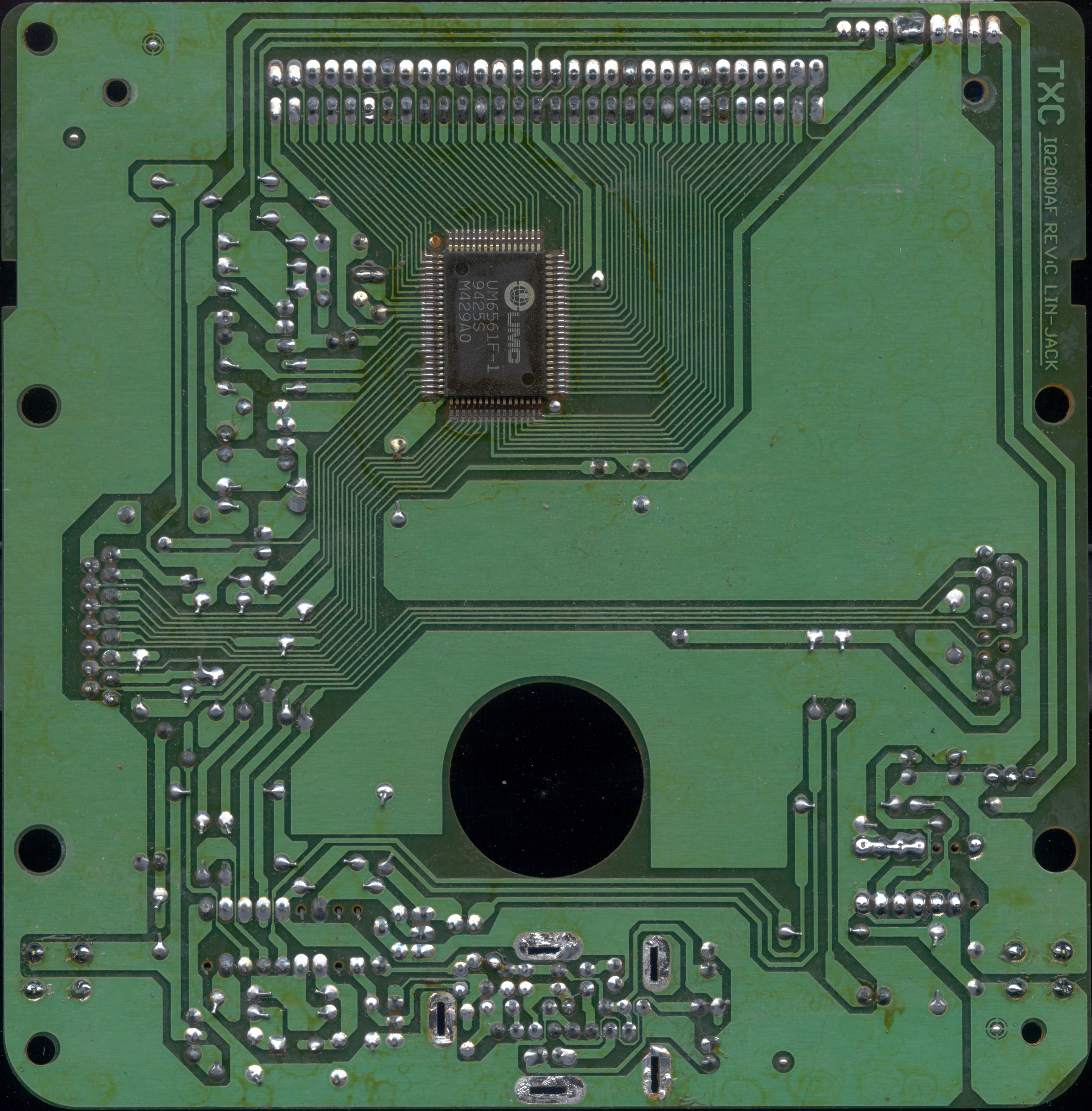
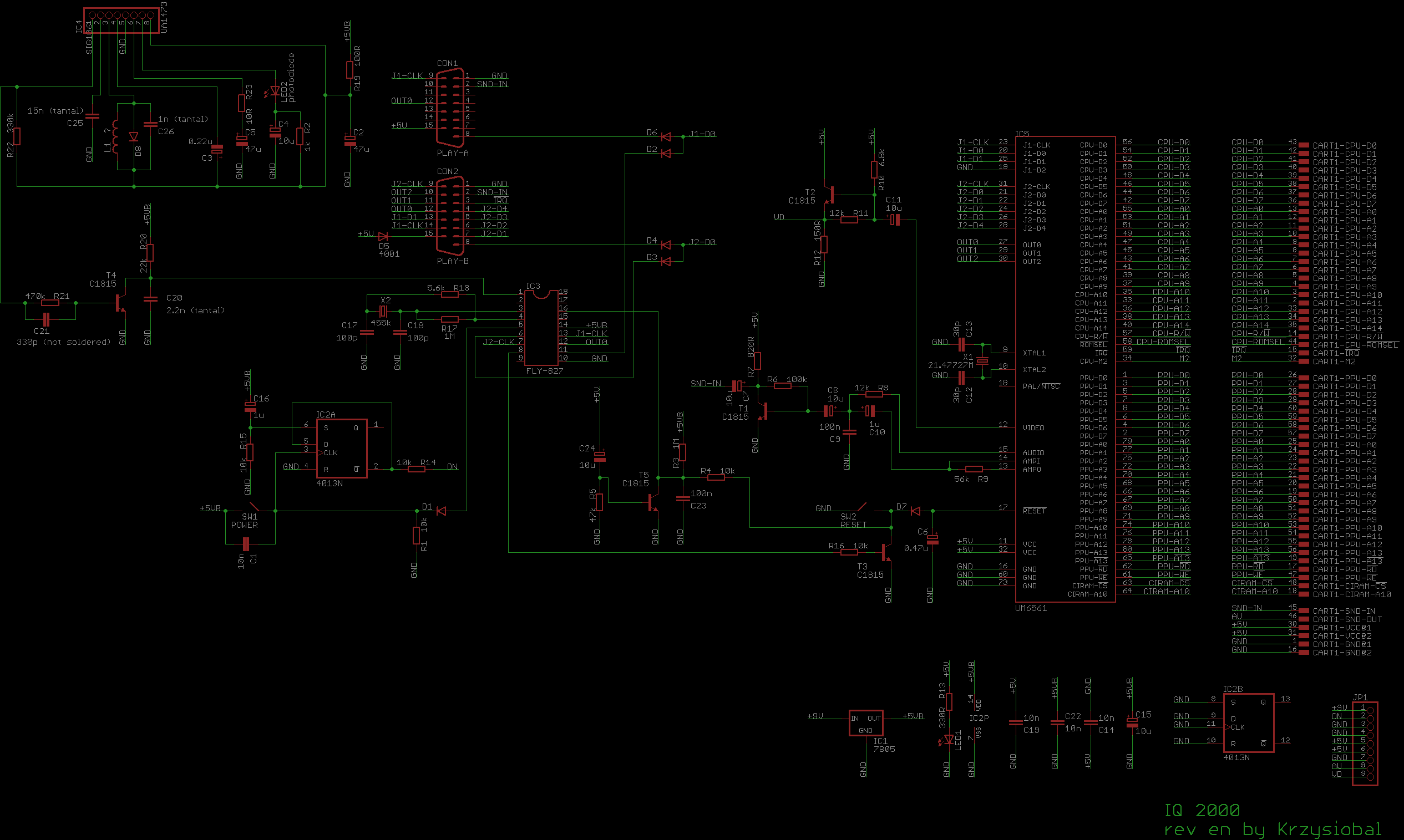
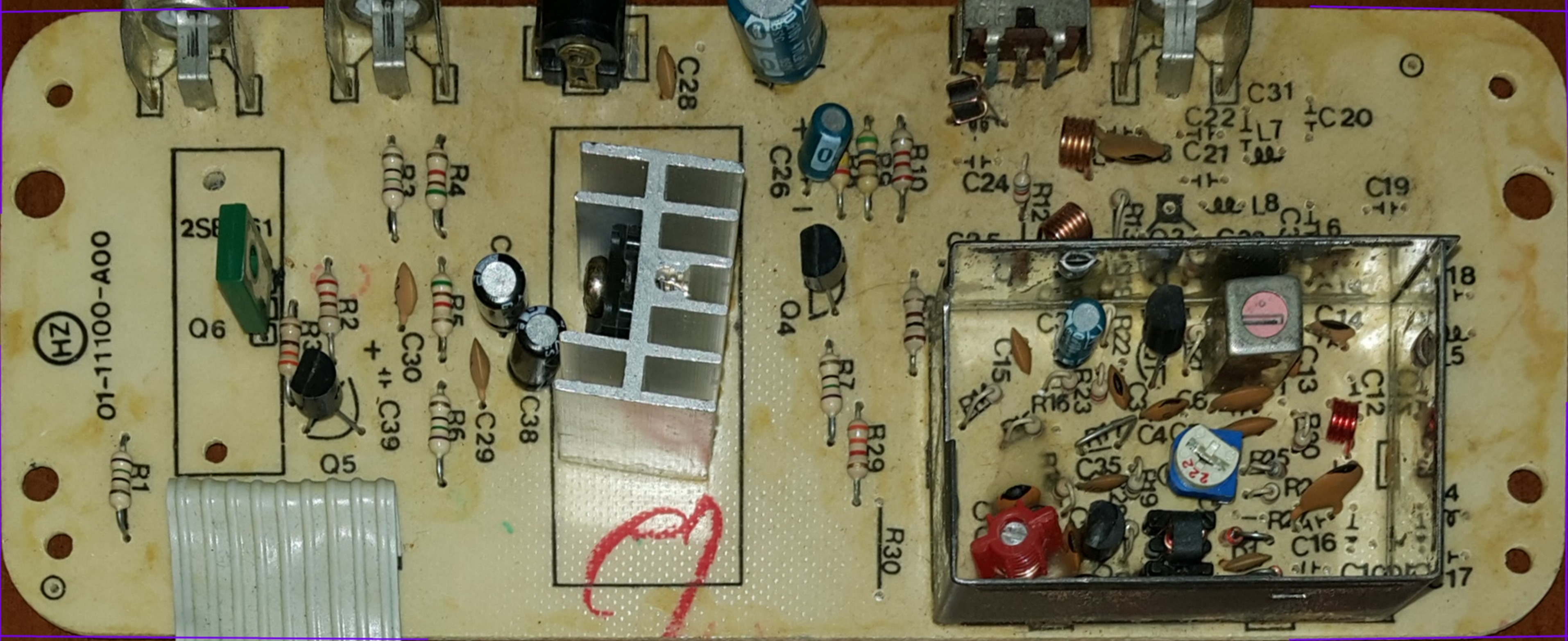
This one uses using single UM6561F-1 NTSC NES-ON-CHIP. Design looks much simpler, altough there are a lot more discrete elements.
Infrared receiver is exactly the same, but the chip (and protocol) used for decoding transmission is different - FLY827. This chip is connected in that way so it can control console's power and reset (remotely restarting or shutting down the console using infrared joypad) - this reveals why they used transistor to control the incoming voltage (although the previous model does NOT have ability to power up/down/restart it remotely).
One of the design flaws is the ivalid connection of R11 transistor (it should be put between T2's B and GND), which results in darker video.
Here what was broken was the tiny 7805 voltage regulator which powers 4013 and infrared chip.


Power supply PCB is exactly the same with two differences:
* they put NPN transistor instead so 4013 need to output 1 instead of 0 to turn the conosle on,
* 7805's radiator is smaller (Nes-On-Chips need a lot less current)

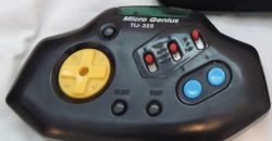
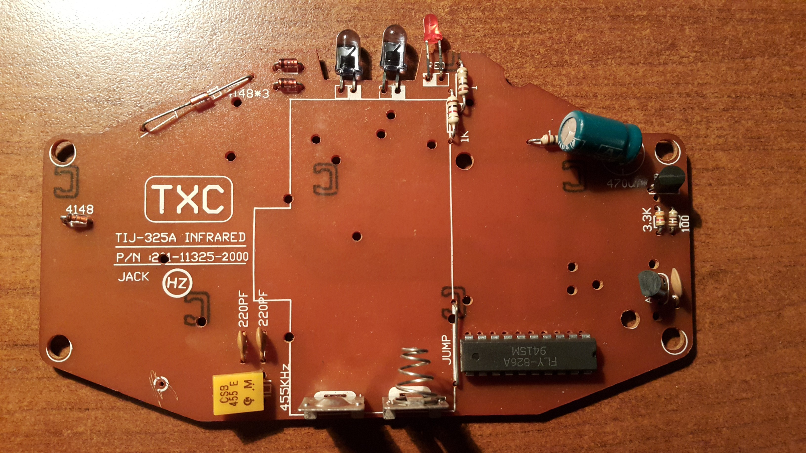
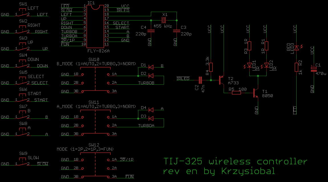
The console is designed to work with two infrared TIJ-325 joypads:


--
Protocols
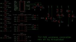
Well, the history begin in fact far far ago, when a friend give me IQ1000 and TIJ-325 joypads and they did not worked together. It was not compatible with that model (which I did not know at that time), so I replaces the FLY047 chip (which I was not able to figure out how works) and the infrared receiver with my own Attyiny13 adapter, plugged in place of the FLY047 chip.
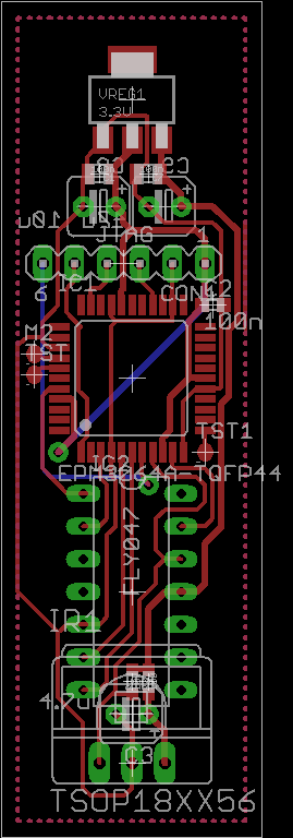
Unfortunatelly I was not able to make it work reliably - the attiny is too slow for communicating with CPU (CLK/OUT0/D) and receiving infrared data. Next approach was to use EPM3064 CPLD which was better choice:
At that time I got that joypad in my hands so I was able to rev-eng partially its protocol, but the 1P/2P/FUN switch in FUN mode was still unknown for me.
Now I have IQ2000 but don't have the joypad, luckily testing all possible combinations of the data I was able to figure out pattern needed to restart/power down the console.
--
pin 1:
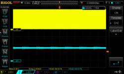
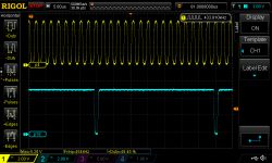
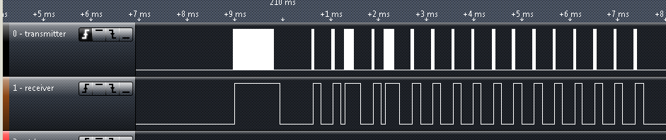
There is a transistor inverter between IR receiver and FLY-827 so:
* ir blinking makes = high signal on its input
* no ir blinking = low signal on its input
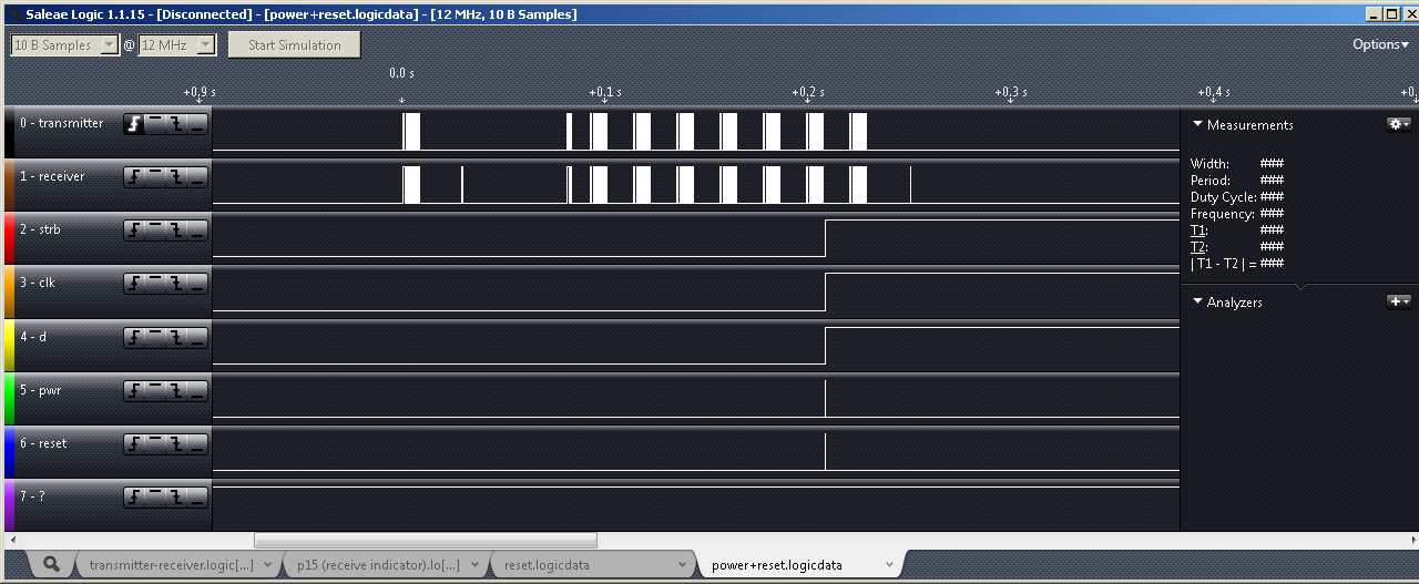
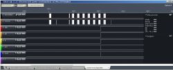
Dependence between transmitter and receiver waveforms: transmitter-receiver.logicdata
pins 3 & 4 - clocks
pin 2 - unknown output? seems to be stuck at +5V (there is internal connection to chip die)
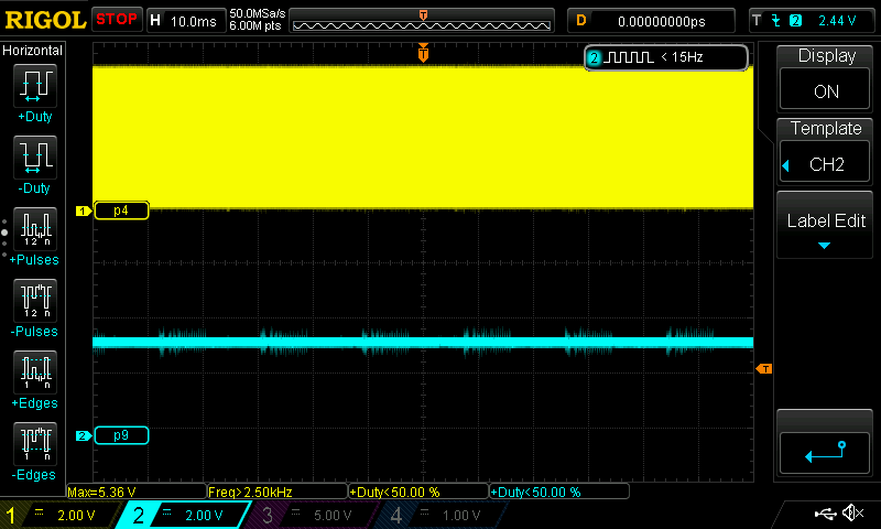
pin 9 - some kind of input?
(there is internal connection to chip die)
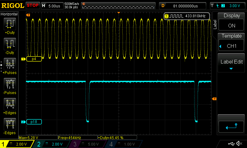
pin 18 - becomes low on every 16th edge of clock
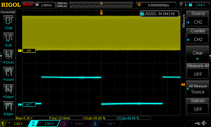
pin 17 -around 54.2Hz square output (more stable if no infrared data is transmitted)

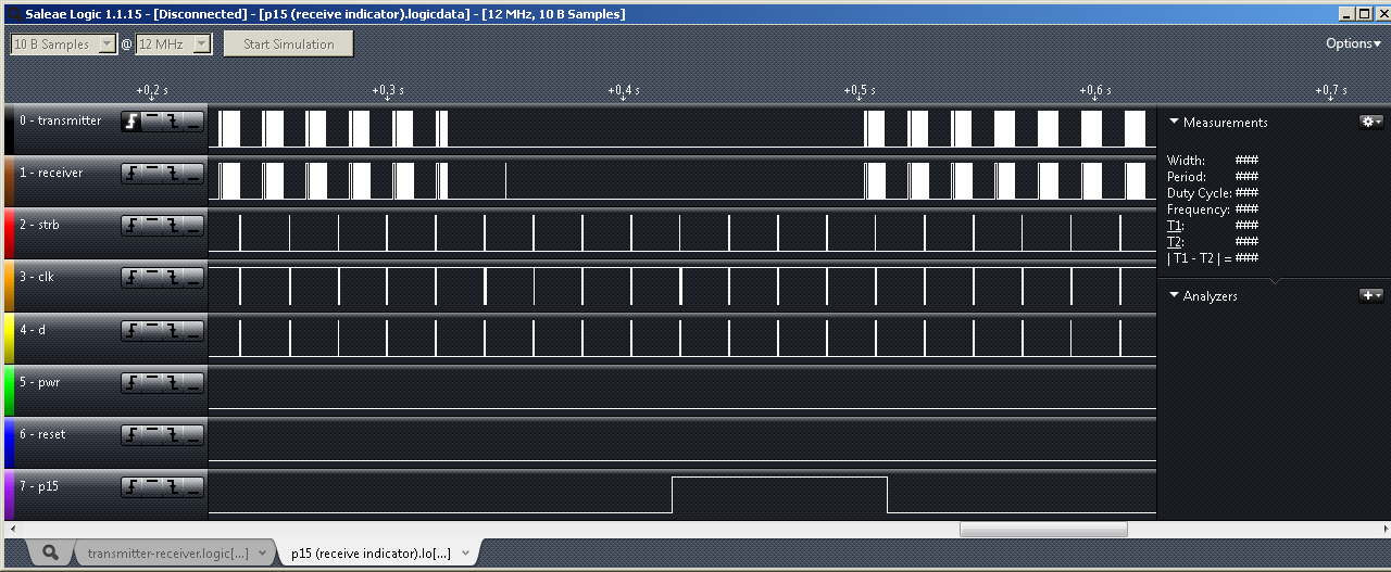
pin 15 - seems to be inactivity indicator (goes high when chips stops receiving data):
* If there is around 111ms or more break with no communication to the transmitter - chip automatically clears all pressed keys for the joypad that did not receive packet
* If chip receives packet with U+D or L+R pressed, that packet is ignored
* if chip receives packet with A+B+R+L+D+U pressed - constant toggling of button start begins (even if pad is not sending anything, stops if invalid packet is received)
* if chip receives 7 packets of FUN + Sta+U+D+L+R - console reset is triggered
* if chip receives 7 packets of FUN + Sel+Sta+U+D+L+R - console power + reset are triggered
IQ 1000
Chip version. Quite weird feature is the use of tact-switch, which clocks 4013 flip floop which controls transistor which passes the +9V, instead of the mechanical switch. The broken element was 4013 (powered directly from +9V), which is the first object that gets hurt when incorrect power supply is plugged.
Instead of putting IR receiver (like the TSOP1838), they prefered ordinary photodiode, some mysterious C1473HA SIL8 chip and a lot of R/L/C/D components, enclosed in a Faraday's cage. Everything is connected to FLY047 chip, which receives the incoming serial joypad data and passes it to CPU.


Here is the power supply PCB with transistors controlling the input voltage:
The console is designed to work with TIJ-309 wireless controller.
IQ 2000
This one uses using single UM6561F-1 NTSC NES-ON-CHIP. Design looks much simpler, altough there are a lot more discrete elements.
Infrared receiver is exactly the same, but the chip (and protocol) used for decoding transmission is different - FLY827. This chip is connected in that way so it can control console's power and reset (remotely restarting or shutting down the console using infrared joypad) - this reveals why they used transistor to control the incoming voltage (although the previous model does NOT have ability to power up/down/restart it remotely).
One of the design flaws is the ivalid connection of R11 transistor (it should be put between T2's B and GND), which results in darker video.
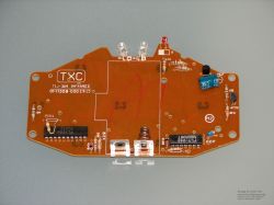
Here what was broken was the tiny 7805 voltage regulator which powers 4013 and infrared chip.

Power supply PCB is exactly the same with two differences:
* they put NPN transistor instead so 4013 need to output 1 instead of 0 to turn the conosle on,
* 7805's radiator is smaller (Nes-On-Chips need a lot less current)
The console is designed to work with two infrared TIJ-325 joypads:

--
Protocols
Well, the history begin in fact far far ago, when a friend give me IQ1000 and TIJ-325 joypads and they did not worked together. It was not compatible with that model (which I did not know at that time), so I replaces the FLY047 chip (which I was not able to figure out how works) and the infrared receiver with my own Attyiny13 adapter, plugged in place of the FLY047 chip.
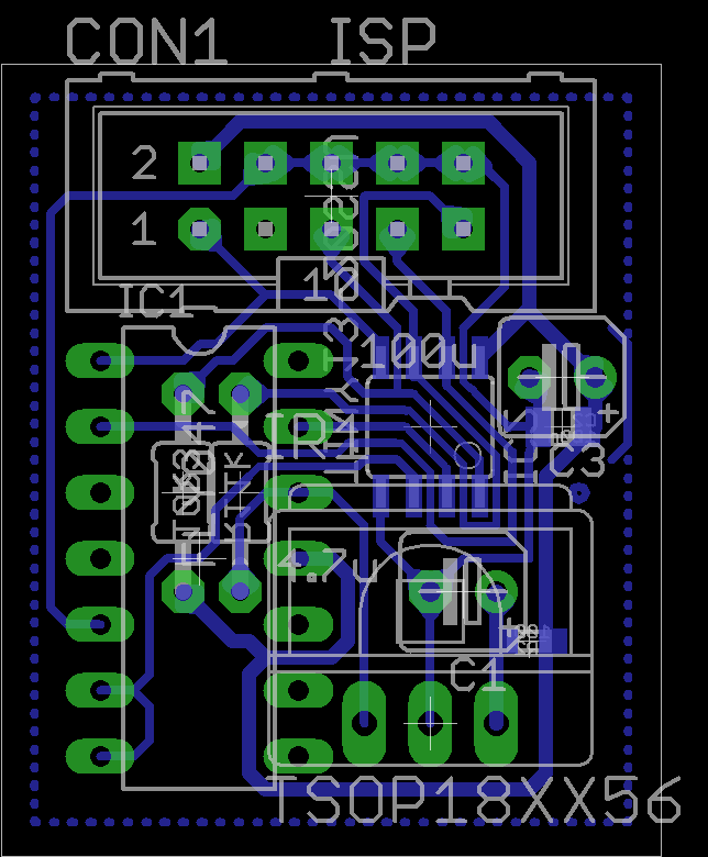
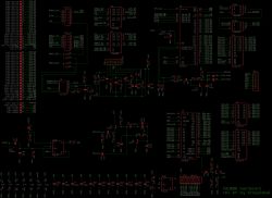
Unfortunatelly I was not able to make it work reliably - the attiny is too slow for communicating with CPU (CLK/OUT0/D) and receiving infrared data. Next approach was to use EPM3064 CPLD which was better choice:
At that time I got that joypad in my hands so I was able to rev-eng partially its protocol, but the 1P/2P/FUN switch in FUN mode was still unknown for me.
Now I have IQ2000 but don't have the joypad, luckily testing all possible combinations of the data I was able to figure out pattern needed to restart/power down the console.
Code:
,---v---.
!REDLED <-|01 20|-- +5V
!SLOW ->|02 19|-> !IRLED
!LEFT ->|03 18|-- XTAL2
!UP ->|04 17|-- XTAL1 (455 kHZ)
!RIGHT ->|05 16|<- !SELECT
!DOWN ->|06 15|<- !START
TURBOB <-|07 14|<- !A
TURBOA <-|08 13|<- !B
!2P/1P ->|09 12|-- GND
!FUN ->|10 11|-- ?
+-------+
FLY-826A 9415M
(found in joypad)
It has the following buttons:
* D-Pad, Start, Select, B, A
* SLOW
* Two sliders selecting A/B behaviour respectively (NORMAL/TURBO/AUTO)
* One slider selecting how pad behaves (as 1 player / as 2 player / function mode)
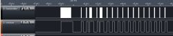
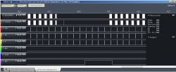
When a button is held (or one of sliders are in AUTO mode), the following pattern is sent continously:
###### ------- ###### -----------------
8.46ms 13.46ms 8.46 ms 55.53 ms
(frame) (break) (frame) (brak)
Each frame (8.46ms) consists of 20 pieces (427us), where each of them can be one of the following:
a = |||||||| (423u)
b = -------- (423u)
c = -------| (367u + 56u)
d = ----|||| (203u + 220u)
Where:
|||| = IR diode blinking at f=56.8 kHZ
---- = IR diode turned off
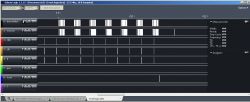
Frame bits (they are transmitted from the left to right)
01234567890123456789
aabc##********cccc**
||||||||||||||||||||
|||||||||||||||||||+- Turbo B (c=off / d=on)
||||||||||||||||||+-- Turbo A (c=off / d=on)
||||||||||||||++++--- ??
|||||||||||||+------- A \
||||||||||||+-------- B |
|||||||||||+--------- R |
||||||||||+---------- L |
|||||||||+----------- D |-c=not pressed / d=pressed (SLOW=ABRLDU pressed at once)
||||||||+------------ U |
|||||||+------------- Sel |
||||||+-------------- Sta /
||||++--------------- cd=player1, dc=player2, dd=function
++++----------------- header
In function mode, it only reacts on pressing start (or select + start) buttons and with.
Start -> FUN + Sta+U+D+L+R+B are pressed at once (with Turbo B and Turbo A pressed too)
Select + Start -> FUN + Sta+Sel+U+D+L+R+B are pressed at once (with Turbo B and Turbo A pressed too)
!REDLED <-|01 20|-- +5V
!SLOW ->|02 19|-> !IRLED
!LEFT ->|03 18|-- XTAL2
!UP ->|04 17|-- XTAL1 (455 kHZ)
!RIGHT ->|05 16|<- !SELECT
!DOWN ->|06 15|<- !START
TURBOB <-|07 14|<- !A
TURBOA <-|08 13|<- !B
!2P/1P ->|09 12|-- GND
!FUN ->|10 11|-- ?
+-------+
FLY-826A 9415M
(found in joypad)
It has the following buttons:
* D-Pad, Start, Select, B, A
* SLOW
* Two sliders selecting A/B behaviour respectively (NORMAL/TURBO/AUTO)
* One slider selecting how pad behaves (as 1 player / as 2 player / function mode)
When a button is held (or one of sliders are in AUTO mode), the following pattern is sent continously:
###### ------- ###### -----------------
8.46ms 13.46ms 8.46 ms 55.53 ms
(frame) (break) (frame) (brak)
Each frame (8.46ms) consists of 20 pieces (427us), where each of them can be one of the following:
a = |||||||| (423u)
b = -------- (423u)
c = -------| (367u + 56u)
d = ----|||| (203u + 220u)
Where:
|||| = IR diode blinking at f=56.8 kHZ
---- = IR diode turned off
Frame bits (they are transmitted from the left to right)
01234567890123456789
aabc##********cccc**
||||||||||||||||||||
|||||||||||||||||||+- Turbo B (c=off / d=on)
||||||||||||||||||+-- Turbo A (c=off / d=on)
||||||||||||||++++--- ??
|||||||||||||+------- A \
||||||||||||+-------- B |
|||||||||||+--------- R |
||||||||||+---------- L |
|||||||||+----------- D |-c=not pressed / d=pressed (SLOW=ABRLDU pressed at once)
||||||||+------------ U |
|||||||+------------- Sel |
||||||+-------------- Sta /
||||++--------------- cd=player1, dc=player2, dd=function
++++----------------- header
In function mode, it only reacts on pressing start (or select + start) buttons and with.
Start -> FUN + Sta+U+D+L+R+B are pressed at once (with Turbo B and Turbo A pressed too)
Select + Start -> FUN + Sta+Sel+U+D+L+R+B are pressed at once (with Turbo B and Turbo A pressed too)
--
Code:
,---v---.
IRLED ->|01 18|-> ?
? --|02 17|-- ?
XTAL1 455k (sine) ->|03 16|<- !RESET
XTAL2 455k (sq) <-|04 15|-- ?
power strobe <-|05 14|-- +5V
P2 D0 <-|06 13|<- P1 CLK
P2 CLK ->|07 12|<- OUT0
reset strobe <-|08 11|-> P1 D0
? --|09 10|-- GND
+-------+
FLY-827A
(found in console)
IRLED ->|01 18|-> ?
? --|02 17|-- ?
XTAL1 455k (sine) ->|03 16|<- !RESET
XTAL2 455k (sq) <-|04 15|-- ?
power strobe <-|05 14|-- +5V
P2 D0 <-|06 13|<- P1 CLK
P2 CLK ->|07 12|<- OUT0
reset strobe <-|08 11|-> P1 D0
? --|09 10|-- GND
+-------+
FLY-827A
(found in console)
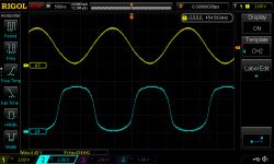
pin 1:
There is a transistor inverter between IR receiver and FLY-827 so:
* ir blinking makes = high signal on its input
* no ir blinking = low signal on its input
Dependence between transmitter and receiver waveforms: transmitter-receiver.logicdata
pins 3 & 4 - clocks
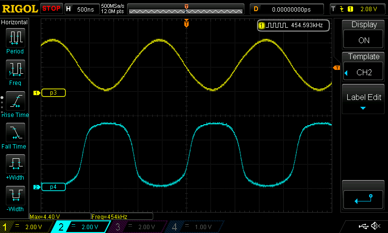
pin 2 - unknown output? seems to be stuck at +5V (there is internal connection to chip die)
pin 9 - some kind of input?
(there is internal connection to chip die)
pin 18 - becomes low on every 16th edge of clock
pin 17 -around 54.2Hz square output (more stable if no infrared data is transmitted)
pin 15 - seems to be inactivity indicator (goes high when chips stops receiving data):
* If there is around 111ms or more break with no communication to the transmitter - chip automatically clears all pressed keys for the joypad that did not receive packet
* If chip receives packet with U+D or L+R pressed, that packet is ignored
* if chip receives packet with A+B+R+L+D+U pressed - constant toggling of button start begins (even if pad is not sending anything, stops if invalid packet is received)
* if chip receives 7 packets of FUN + Sta+U+D+L+R - console reset is triggered
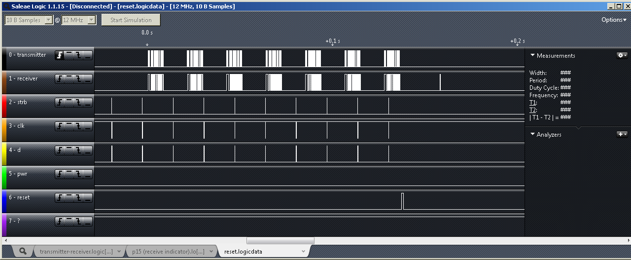
* if chip receives 7 packets of FUN + Sel+Sta+U+D+L+R - console power + reset are triggered