I have recently acquired a few recently made pirate cart for the famicom with some pretty interesting game on them and found out that they could only work properly on NOAC based famiclone. I got curious as to what could make them not work on the genuine hardware... I could understand that there might be timing issue if a game was coded and tested using clone system only but I was wondering about a MMC3 based multicart (best multicart ever as a side note, with plenty of awesome game included). The sound is working perfectly but the menu GFX are all garbled. I would have thought that selecting one of the game in the menu and starting it would fix the GFX seeing as most of the game are pirate copy of licensed game that were made and coded for genuine famicom and nintendo but to my surprise the game also boot with messed up GFX. Is it because of the custom mapper they use? I would expect issue playing certain cart on famiclone but not the opposite, it was a surprise to learn that it is common with newer pirate game.
Thanks
Nothing unless the game is meant to only run with a specific NOAC which expands upon the hardware. Very unlikely. Your Nintendo (tm) hardware probably makes bad contact with the cart.
I made sure that the contact were lining up properly with the famicom adapter (as those cart have shorter edge connector than usual) and tested with a multimeter to verify that the contact were connecting properly between the cart and the adapter. It seem to be a common thing these day and different people confirmed that some newer cart are incompatible with genuine hardware. Like you said it would make sense if they were coded for special clone with extended capability but the same cart will work on any NOAC clone, even the retroduo which as far as I know has nothing special to it. The seller told me that it doesn't work on the genuine famicom either. That's why I'm confused as to what could cause this incompatibilty with licensed hardware...
SkinnyV wrote:
I have recently acquired a few recently made pirate cart for the famicom with some pretty interesting game on them and found out that they could only work properly on NOAC based famiclone. I got curious as to what could make them not work on the genuine hardware...
<snip>
Can you provide some pictures of what the PCB looks like? I'm curious about what they did.
Without a picture of the PCB, my first guess is that they miswired some of the PPU-side enable signals so that it works on the same kind of hardware where four-screen games don't work.
Here you go, if they're not clear enough let me know and I will try to take some more pictures later as those were taken quickly for my personal reference while I was opening the cart yesterday before knowing someone would need to check them out:
http://www.skinnyv.com/Cart/245in1/
As you can see the edge connector is not like the regular one but even though it is shorter, contact are still made, each pins seem to line up perfectly with the Famicom connector and confirmed with a continuity tester on numerous pin.
Edit: I re-taken the pic and those are most likely going to be more visible and clear.
SkinnyV wrote:
Here you go, if they're not clear enough let me know and I will try to take some more pictures later as those were taken quickly for my personal reference while I was opening the cart yesterday before knowing someone would need to check them out:
http://www.skinnyv.com/Cart/245in1/As you can see the edge connector is not like the regular one but even though it is shorter, contact are still made, each pins seem to line up perfectly with the Famicom connector and confirmed with a continuity tester on numerous pin.
Edit: I re-taken the pic and those are most likely going to be more visible and clear.
Ahh very good. Thanks for the pictures.
On the board are a spansion S29GL128 which is a 128Mbit (16Mbyte) flash ROM and a CY62128 which is a 128K*8 SRAM. That's pretty interesting technology for a pirate cartridge.
I have a good theory now as to why this cart doesn't work on a real NES/famicom... The flash ROM is 3.0V only (that diode is being used as a ghetto voltage "regulator" for the flash ROM). The real fami/nes probably cannot reliably read the 3V logic signals coming from the ROM.
It looks like they had it set up for two diodes in series, but instead placed a single zener? diode across pads for the two diodes (marked "D1" and "D2"). It's almost certainly a zener, because the cathode I think is going to 5V. I am amazed this even works, considering the data bus is going to have 5V level logic on it and the chip's VCC is around 3V. I guess for a regulation Nintendo console it doesn't. hehe.
I have to say, I *have* seen the two diode VCC dropper once before. Memblers has a large multicart that used a 3.3V ROM and had two diodes in series with VCC to drop 5V down to around 3.3V for it. I successfully dumped this cart using CopyNES and it emulates just fine... it also ran OK on a real NES.
Thansk alot for checking it up. If there is any modification I could make to the cart to make it work I would be very happy. Do you think it would as simple as adding an extra zenner diode on the extra empty pad to make it work properly on a NES? I need to take a closer look but I don't remember this pad being connected to anything and I can't be certain by only looking at the picture as the boarder is around this area . Or do you think adding a proper voltage regulator circuit would be preferable? I know it's just a mutlicart but it is pretty much the best one I ever came accross and would be thrilled to fix it as it would also give hope for some of the other cart I ordered that are incompatible with genuine hardware like this one. I'll post the list of game later and people will understand my motivation for fixing this particular one though:) No repetition at all, game varying from older classic game to newer one like Ninja Gaiden 2 and Double Dragon 3 along with a few pirate original like Alladin.
SkinnyV wrote:
Thansk alot for checking it up. If there is any modification I could make to the cart to make it work I would be very happy. Do you think it would as simple as adding an extra zenner diode on the extra empty pad to make it work properly on a NES? I need to take a closer look but I don't remember this pad being connected to anything and I can't be certain by only looking at the picture as the boarder is around this area . Or do you think adding a proper voltage regulator circuit would be preferable? I know it's just a mutlicart but it is pretty much the best one I ever came accross and would be thrilled to fix it as it would also give hope for some of the other cart I ordered that are incompatible with genuine hardware like this one. I'll post the list of game later and people will understand my motivation for fixing this particular one though:) No repetition at all, game varying from older classic game to newer one like Ninja Gaiden 2 and Double Dragon 3 along with a few pirate original like Alladin.
Unfortunately I don't think it will work on a real NES without level translation logic on at least the data lines. Dumping the cartridge might be possible though, but it'd require removal of the flash ROM and then that could be dumped using a programmer of some form probably. Messy though. It might be possible to dump using a copynes but I suspect the ROM data will come out corrupted due to the possibly incompatible logic levels.
That's too bad... I was planning on dumping the flash but I'm not sure if it's worth it. I guess i can just play it on a clone, I just don't like having a crap console just to play one multicart. I also bought one extra for my brother who recently purchased an old nes while feeling nostalgic and he wouldn't be able to use it. That's also one of the reason I really wanted to fix it for regular hardware:) And that logic translation stuff is beyond my electronic level so unless I follow instruction I wouldn't be able to come up with it. Thanks anyway for the help!
If you want to use it on a NES, shouldn't you be able to get a Gyromite 60-72 pin adapter and modify it for the level translation to 5v and slap it into a NES cart?
I already have two 60 to 72 pin adapter but Kevin seem to say it's not possible to just fix it with voltage regulation. That's basically what I was trying to do, find a way to modify the circuit to make it compatible with regular Nes and Famicom. If I knew what to modify I would but according to Kevin last post, it seemed more complicated than just fixing the voltage. Unless I misunderstood his last message? If there was a way, I would be very happy to try it though but I wouldn’t be able figure out what to do on my own if it requires logic translation. Unless it sound more complicated than it really is?
SkinnyV wrote:
I already have two 60 to 72 pin adapter but Kevin seem to say it's not possible to just fix it with voltage regulation. That's basically what I was trying to do, find a way to modify the circuit to make it compatible with regular Nes and Famicom. If I knew what to modify I would but according to Kevin last post, it seemed more complicated than just fixing the voltage. Unless I misunderstood his last message? If there was a way, I would be very happy to try it though but I wouldn’t be able figure out what to do on my own if it requires logic translation. Unless it sound more complicated than it really is?
Actually I just talked to Memblers about it and he said that the original post claims the games/menu actually work, but it's just bad graphics. I must've missed that before. That tells me that it's a VRAM problem instead of a flash problem. The cartridge has 128K of VRAM on it which presumably gets loaded by the menu from the flash before the game is started. I have two theories here on what might be causing that problem.
The first theory is that the RAM chip is too fast and is being loaded with some kind of garbage or bad data... The test there is to replace it with another 128K SRAM that's slower. It has the usual pinout for a 128K byte SRAM so subbing another part wouldn't be terrible. but before trying that, I had another theory.
And that theory is there's absolutely no bypass capacitors on the board. Maybe adding a .1uf capacitor across power and ground on the SRAM might fix it? One time I had a Dizzy cart that didn't work because there was no bypass capacitor. The game would start, and as the logo was dropping on the screen, it'd just lock up. Every single time.
Adding the capacitor (there was even a spot for it, but it was not populated) made the cartridge work properly. If you add one, add it
across the power pins of the RAM directly. Tack it on, and test. if it works then you can worry about making it look pretty and all that.
So I just connect a 1.uf cap between VCC and GND (which should be pin 1 and pin 32 according to datasheet) on the RAM chip? I'll try when I get home. Will let you know how it goes!
Edit: ok I re-checked the datasheet and either I didn't look properly the first time or it was the wrong datasheet, but it was actually pin 32 and 16. I tried it and it didn't fix the garbled gfx unfortunatly. I would like to test the ram theory but I don't think I have ram chip like that lating around, probably only have 64k ram.
Here what I did:
http://www.skinnyv.com/Cart/245in1/cap.JPG
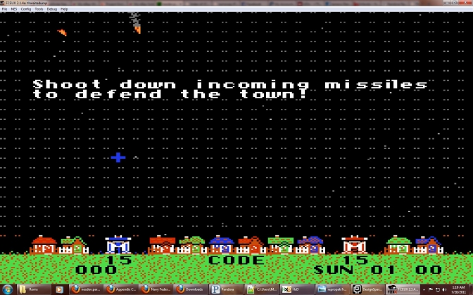
And here an example of the GFX corruption I get, this is not the menu but from some beat them up type of game:
http://www.skinnyv.com/Cart/245in1/screenshot.JPG
Looking up that RAM chip, the V means it's a 3.3V type. It's been known for a while that the NES CPU seems to work OK when taking 3.3V inputs (otherwise the PowerPak wouldn't work). I've been curious if the PPU would be the same, I'm not aware of it being tested, so maybe that doesn't work? In that case, logic level translation on the CHR bus should fix it. Or replacing it with a 5V part, and have it actually running at 5V.
I guess the easiest thing for me would be to try to locate a similar ram chip that use 5v then. I'll look around the net tomorrow and try to order one. But I seem to remember that finding 5v IC was much harder nowadays... Is it a matter of just swapping the part with matching pinout or is there anything else needed to make the 5v IC work on this specific PCB?
It's easy to find a replacement chip at 5V because it's in an SMD package.
CY62128ELLat Mouser for $3.62
CY62128ELL at DigiKey for $3.54
SkinnyV wrote:
I guess the easiest thing for me would be to try to locate a similar ram chip that use 5v then. I'll look around the new tomorrow and try to order one. But I seem to remember that finding 5v IC was much harder nowadays... Is it a matter of just swapping the part with matching pinout or is there anything else needed to make the 5v IC work on this specific PCB?
You'd need to change VCC of the chip to 5V since it seems they are running it on 3V also. You can lift pin 32 and run it to 5V coming from the cartridge edge pins. Nothing else should need to be changed I don't think. It might be advantageous to check the datasheet for the RAM though to make sure that 3V inputs (if the mapper also runs at 3V) can drive it.
Good call on the Vcc supply, didn't even think about that.
As for the inputs at 3V that should be OK as long as they really are 3V. Here's what the
datasheet has to say:
Vih (Input HIGH Voltage) For VCC = 4.5 V to 5.5 V : Min=2.2 V Max=VCC + 0.5 V
qbradq wrote:
Good call on the Vcc supply, didn't even think about that.
As for the inputs at 3V that should be OK as long as they really are 3V. Here's what the
datasheet has to say:
Vih (Input HIGH Voltage) For VCC = 4.5 V to 5.5 V : Min=2.2 V Max=VCC + 0.5 V
Yeah that's fine then. The mapper will certainly swing between 0V and 3V (if it indeed runs on 3V) since it's CMOS.
Well thanks guys, I'm ordering right away and will keep you updated!
Ok, finally got the ram after a long delay partly caused by me ordering directly from the link posted without looking at the detail. Ended up ordering the TSOP version so I had to redo the order once I got the first one.
I swapped the ram chip for the new one. Lifted pin 32 to connect it to 5v . Correct me if I'm wrong though but wasn't pin 32 already connected to 5v before doing the mod? So in any case I still lifted pin 32 and ran a wire directly to one of the 5V edge pin just in case I missed something. The result was a somewhat more readable menu and less corrupted GFX but still corrupted. The was improvement but still doesn't make the cart working properly. I tried adding the capacitor like suggested between VCC and Ground but no improvement. I even redid the solder job a second time just to be sure (it looked very well done the first time tough) and still same result.
Here is the result:
Menu before modification:
http://www.skinnyv.com/Cart/245in1/Menu_Before.JPG
Menu After RAM replacement:
http://www.skinnyv.com/Cart/245in1/Menu_After.JPG
Game Before modification (Sunsoft's Batman):
http://www.skinnyv.com/Cart/245in1/Game_Before.JPG
Game after RAM replacement:
http://www.skinnyv.com/Cart/245in1/Game_After.JPG
Replaced chip:
http://www.skinnyv.com/Cart/245in1/ramswap.JPG
As you can see there was definitely an improvement! But still not usable unfortunately.
Do you have floating address pins on the RAM?
Doesn't seem like there's any.
Run one of your fingers on the pins of the RAM chip while looking at the screen. If any of them are loose it will pick the noise from your finger and the corrupted pattern on the screen will change in response to the RAM picking the 60hz (or 50 if you're in EU or AU) from your finger.
It sure looks muuuuuch better than before. The fix could be something silly like adding an pullup on the PPU data lines.
Looks like you're only one CHR line away. I'd check for continuity with a multimeter if you've got one on all the signals/pins.
If he had data lines problems he would have vertical stripes. If he had address lines problems he would have garbled graphics. The fact it's RAM doesn't help at all as the NES writes the actual graphical data on the chip...
I must confess I'm a bit confused after seeing the horizontal lines pattern...
It's almost like if the cartridge program was trying to write to the VRAM without waiting for the PPU to be ready to take the writes.
What happens when you lower the CPU/PPU power supply to say 4.5V ?
I did test for continuity and everything seem good. As for the pattern there are not really horizontal, it really depend because the corruption can vary on the menu. As for lowering voltage I'm not really sure how to achieve that safely. But one thing is that I managed to get an almost perfect menu yesterday so I'll see if the adapter is not responsible for the rest of the corruption as the edge pin connector of those pirate carts are really short. I might try to solder the cart directly to the adapter to rule out the bad contact theory even though I tested most of the pin for continuity and didn't see a problem.
Is the corruption pattern different every time you start the cart or every frame?
The corruption pattern can change when I power cycle or reset the NES. The picture of the menu after the mode is one of the lucky time it wasn't so bad. I even was able to briefly get an almost perfect menu yesterday but when I booted a game is was as unplayable. I tough it might be the connection with the 60 to 72 pic adapter even though I tested with multimeter so to completely rule that out I soldered it directed to one of the adapter like this:
http://skinnyv.com/Cart/245in1/Direct_Connect.JPG
Test each connection with a multimeter for continuity and for short. All was perfect. Tested it ion my NES, corrupted graphic, and not the nice one like on the picture. I must say it is a very strange cart.
So I'm at a loss once again:) By the way, I was still wondering about the VCC, I've been instructed to lift the RAM's VCC pin and connect to +5v on edge connector but I don't think it was running on 3V at all, it seem to be connected directly to pin 30 of the Famicom edge connector which, as far as I know is 5v...
So I've actually got a similar failure with the horizontal lines playing around with my kazzo and a SRAM NROM cart.
It turns out dumping the cart and comparing hex files, that the very first byte in CHR memory is corrupt. It's 0xA0 and supposed to be 0x00. I still haven't figured out why exactly. But I had a similar problem where the first byte in PRG memory was programming improperly. It ended up fixing it's self when I realized the retrozone cart I was using had the /CE line on the PRG memory tied to GND. So basically anything that was being write controlled by PRG /CE was failing, but writes that were controlled by PRG /WR were working properly. Connecting the /CE pin to PRG /CE actually fixed a lot of other problems I had too with corrupt data and in ability to battery back my SRAM well also.
I don't know if all this helps much but it's one way I was able to get horizonal lines with a completely different setup. My error is in the writing process to the SRAM not reading it. Basically it makes me think that it's corrupting data for something like the first byte of several or most tiles or something. That gives a horizontal line and the follow on bytes of the tile or block of memory program properly. IDK I'm making a lot of guesses on how things are actually working but it sounds possible to me atleast.
When you checked all the lines did you compare it to the pin out of the SRAM? Like did you ensure the /CE line is actually connected to CHR A13 on the cart edge? I would recommend checking all the control signals making sure they make sense where they wire them up. That's basically why I had issues, the board is designed for EPROM or FLASH where it wouldn't be an issue grounding /CE and not letting the NES actually enable the chip. But it caused hell with my SRAM even though the pinout was the same. I know it's a different story on the CHR side with VRAM and all but it atleast gives you something to look at. Perhaps if I find my error on the CHR side it'll be related to yours as well, I haven't figured out why I'm having an issue with that first byte...
The VRAM's /CE1 line is going to the mapper. The /CE2 is connected to +5V.
Is it just me or is it strange the mapper is controlling /CE? /CE is normally A13 from what I'm used to but this isn't a standard mapper either.
What about write and output enable? I would imagine the NES has control of those...
VRAM'S /WE is conntected to famicom pin 47 CHR RAM WR. As for VRAM'S /OE, my multimeter is telling me it's connected to ground and +5v but I wil lrecheck this one as I was rushing.
SkinnyV wrote:
VRAM'S /WE is conntected to famicom pin 47 CHR RAM WR. As for VRAM'S /OE, my multimeter is telling me it's connected to ground and +5v but I wil lrecheck this one as I was rushing.
I can see /OE grounded, it doesn't allow for making use of CHR /RD signal but it's not of much concern.
So what does CHR A13 line do? This is should basically one of the /CE signals for the VRAM. Double check to see if it's tied to either of the /CE pins on the SRAM.
If it's not connected I'm really surprised now that I think about it a little more. The /CE line MUST be low when writing or reading to/from VRAM, and it only makes sense for what's tring to Read and Write (the NES) to have control of /CE. For the mapper to have complete control of /CE the mapper basically doesn't give control where it belongs. If this is really the case it's a backasswards design and super difficult to time properly. I'm suprised it even works in a clone... Based on the fact you're getting different glitches every time supports the possibility of a timing issue, since the Mapper can't very well know what to do with /CE when.
I'd be curious what would happen if you connected CHR A13 to the spare /CE2 that's currently tied to Vcc. If it wasn't obvious you'd want to make sure you cut a trace or somehow removed it from Vcc, you could double check by checking the resistance of the CHR A13 line to Vcc afterwards and ensure it wasn't low (like less than 1K ohms).
I didn't check the datasheet for this part, but the 2nd CE line almost certainly a positive-enable, so it being at +5V has it enabled (both CE's must be enabled).
So if the VCC pin for the RAM is at 5V, then I guess they were running the original 3V RAM chip at that.. strange.
There's nothing stopping the mapper from taking CHR A13 (or /A13) and then having it's own output to the CHR /CE on the RAM. The only reason I can think of for doing that, is if the mapper was also controlling the "CIRAM /CE", then it could map nametables into it's the cart's CHR-RAM (which would allow 4-screen mode, and nametable banking, which are kinda rare features).
I wonder, is the voltage of the clone really 5V? Maybe NES maskROMs and mappers can run at 3.3V, I can't say I've tried it or would know what to expect.
infiniteneslives wrote:
For the mapper to have complete control of /CE the mapper basically doesn't give control where it belongs.
This is true in the case of one CHR memory. But when you have a split CHR ROM (e.g.
mapper 68), or both CHR ROM and CHR RAM (e.g.
TQROM or
its Chinese clone), or allowing nametables and pattern tables to share one memory as Memblers mentioned (also mapper 68), you need the mapper to postprocess the PA10-PA13 to come up with the enables for CHR memories.
Memblers wrote:
There's nothing stopping the mapper from taking CHR A13 (or /A13) and then having it's own output to the CHR /CE on the RAM. The only reason I can think of for doing that, is if the mapper was also controlling the "CIRAM /CE", then it could map nametables into it's the cart's CHR-RAM (which would allow 4-screen mode, and nametable banking, which are kinda rare features).
Ahh yeah, it all makes sense now. Thanks for getting back on the straight and narrow guys.
I did some test now that I got back my Yobo NOAC clone and it definitely look like the clone is not outputting as much power as a real Nintendo system. I don't have exact value as I did it in a rush this afternoon but voltage was lower on the clone.
Still no luck yet running the cart on real nes though!
Oh yea, I should have mentioned that. My Yobo outputs 4.7 V when I use the supplied wall wart. Using my own 5.5v wall wart it outputs over 5v, but not quite 5.5v. I never tested the leads on the warts, I should probably do that.
Anyway, I did notice that CV3 does not boot at all when using the wall wart supplied with the Yobo (goes to grey screen). It does boot when using mine, but fails to enter game play due to the CIRAM bug.
Sorry to necrobump, but was this ever figured out? Couldn't you just add a voltage regulator to the Vcc line on the chip, and drop it down to 3.3v that way?
It was unfortunatly never resolved, I just shelved thoses 2 cool cart and I now consider them a loss.
With a help from our friend from polish forum dic-sc7, we found a solution to make this cart working on real hardware (Famicom/NES). All you need to do is simply desolder OE pin from CHR-RAM and solder it to unused CHR/RD pin 17:

Wtf, after all the crazy shit I tried with that cart (soldering directly to a famicom adapter, replacing ram with 5V IC etc...) I can say that this simple mod seem to make the cart work perfectly on a North American NES.
Dziękuję! Go poland!

infiniteneslives wrote:
I can see /OE grounded, it doesn't allow for making use of CHR /RD signal but it's not of much concern.
So close, but so far away...
The famiclone had no address/data multiplexing, so no bus conflict. Oops.
Has anyone ever figured this out? I bought 2 copies, one for my brother and the other for myself, but I am at an impasse with how to get them running on genuine Nintendo systems. If anyone is interested, I can send the boards to you to hack on.
Quote:
Has anyone ever figured this out? I bought 2 copies, one for my brother and the other for myself, but I am at an impasse with how to get them running on genuine Nintendo systems. If anyone is interested, I can send the boards to you to hack on.
The answer is only a few posts back...

Rocket wrote:
With a help from our friend from polish forum dic-sc7, we found a solution to make this cart working on real hardware (Famicom/NES). All you need to do is simply desolder OE pin from CHR-RAM and solder it to unused CHR/RD pin 17:
I did that, and it did nothing to get this running. That only apparently works on the 150 in 1.
I tried it with the specific cart discussed in this thread and it work perfectly. You have to lift the /OE pin from the pad and then wire it to /CHR-RD on the cart connector. If you just wire it without lifting the pin it doesn't work.
SkinnyV if you don't mind me asking, where can you get this particular multicart?
I got 2 from a user on another forum.
SkinnyV: I have given up on my carts. If you're willing, I could pay you to get mine functioning. I would hate to feel like I wasted money on buying them, and with as many games as are on them, I am cool spending a bit more to get them working.
Remember that you can save on shipping by opening the cartridge and sending only the PCB, not the shell.
If it's only for your personal copy, I will do it for free if you are unable to do it yourself.
I have some cartridge like this(PPU /RD not connect to the VROM or CRAM)!
see the photos
front(cartridge pin 17 not connected)
http://i.imgur.com/I5OqdS8.jpgback
http://i.imgur.com/NVQHIRk.jpgI found on my dumper device,it can read the vrom data,and write the cram,but on real famicom,can not read the vrom(read/write cram) data correct.
When I dumped the rom use tapedump and chip-on-board famicom,then the rom can work on emu correct.
byemu wrote:
I have some cartridge like this(PPU /RD not connect to the VROM or CRAM)!
see the photos
front(cartridge pin 17 not connected)
http://i.imgur.com/I5OqdS8.jpgback
http://i.imgur.com/NVQHIRk.jpgI found on my dumper device,it can read the vrom data,and write the cram,but on real famicom,can not read the vrom(read/write cram) data correct.
When I dumped the rom use tapedump and chip-on-board famicom,then the rom can work on emu correct.
I'm currently trying to figure out how to make work a cartridge who works on noac on my famiclone. Lifted pin 24 (OE) from CHR-RAM (chip km681000blg, who is a cmos sram) and pin 24 from a hy6264alj-10 chip ( also a sram) and use a wire soldered to pin 17 of the cartridge, but no results, glitched menu, and glitched games.
Sorry for reviving an old post, but, I don't know what else can I do for this problem.
Unless you are talking about the same cart that was discussed in this thread, it might be easier if you would show hi-def scan of both side of the PCB and also describe a bit what is happening.