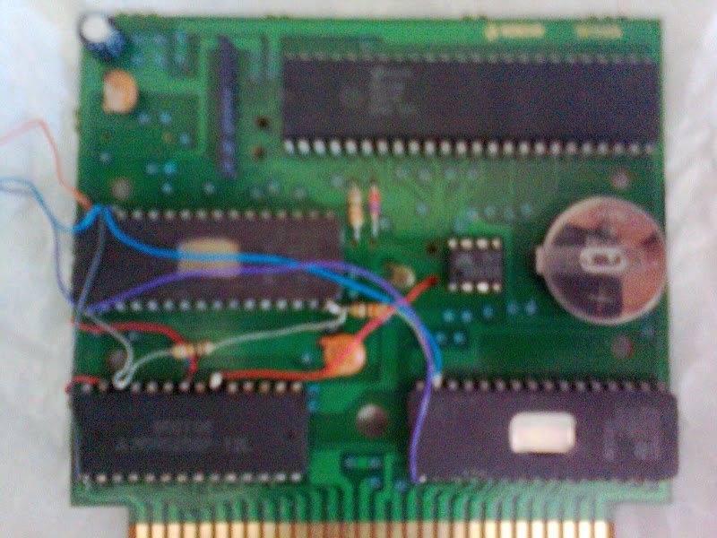
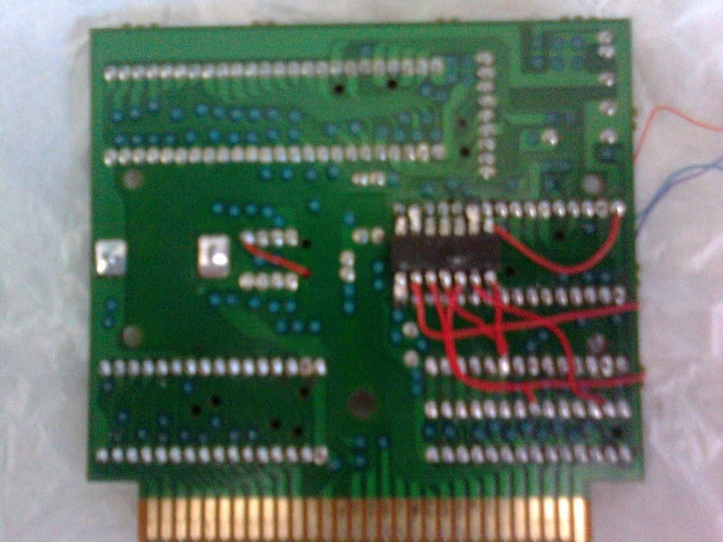
VRC-VI multicart

This is an archive of a topic from NESdev BBS, taken in mid-October 2019 before a server upgrade.
View original topic
VRC-VI multicart
by on (#81508)
Front:
Image

Back:
Image
The final board layout has three more chips for the game select circuit. The SRAM chip is large enough to keep saves for the 4 game slots. The pictured chip behind the workram is a 74LS32 used to OR the write and output enable pins for the 62256 chip (to make it behave same as an 6264 chip) so I can have 4 8KB banks. Akumajou Densetsu does not care if WRAM is present or not so it just works...) SRAM banks swap along with ROM banks so each game saves on it's own slot. At the time the picture was made I was using an 3 position pole switch to select the game but I thought it would be a SHAME to drill the beautiful Madara cartridge and that made me put more chips in for the game select circuit.


The three existing VRC-VI games cycle in the following order when reset is pressed:

Moryou Senki Madara (original game for that board)
Esper Dream 2
Akumajou Densetsu
(an 512KB unused bank is left empty unfortunately and the counter is programmed to skip this bank)

The games are translated to english, Akumajou Densetsu had it's progam rom modified to become compatible with the mapper 26 (VRC6 V). Not a single copper track of the original board was cut or scratched, therefore the mod can be undone if I deem necessary. But honestly I doubt I'll ever do that. I am keeping the original mask roms in a safe place though. ;)

And sorry about the AWFUL pictures from a cheap cell phone...

by on (#81510)
Wow, that's really cool :D I look forward to seeing more of your work!

by on (#81511)
Its really nice to see you here ^^
Re: VRC-VI multicart
by on (#109091)
I am necro-posting this thread to ask a couple of questions on parts... :mrgreen: what are the 3 non-pictured ones?

Is the HM62256BLP-7 a good SRAM chip for the cart? datasheet
Also would a SMT 74F32 work the same as the 74LS32? datasheet I can see the F is faster and smaller :lol:

TIA!
Re: VRC-VI multicart
by on (#109093)
keropi wrote:
I am necro-posting this thread to ask a couple of questions on parts... :mrgreen: what are the 3 non-pictured ones?

Is the HM62256BLP-7 a good SRAM chip for the cart? datasheet
Also would a SMT 74F32 work the same as the 74LS32? datasheet I can see the F is faster and smaller :lol:

TIA!


The SRAM looks fine, the 74F32 should work fine too as it will be used on the standard 5V supply from the Famicom, not draining any current from the SRAM power circuit. The only reason you're changing from the original 6264 chip is so you can have four 8KB pages for the four games you're going to put into the cart. :)

I used a 74LS393 as counter on my cart. (I had it laying around. I tend to make things with random stuff I grab from my parts drawer ... lol)
Re: VRC-VI multicart
by on (#109096)
Thanks for the info l_oliveira :mrgreen:
I hope I succeed in making a similar cart :roll:
Re: VRC-VI multicart
by on (#109098)
keropi wrote:
Thanks for the info l_oliveira :mrgreen:
I hope I succeed in making a similar cart :roll:


You will ! I am sure !
Re: VRC-VI multicart
by on (#109104)
^ yes, I'll have awesome help :mrgreen:
Re: VRC-VI multicart
by on (#109114)
Be careful about the F series logic; it is substantially higher input current (and also simply consumes more power in general) and may not play with CMOS parts.
Re: VRC-VI multicart
by on (#109138)
lidnariq wrote:
Be careful about the F series logic; it is substantially higher input current (and also simply consumes more power in general) and may not play with CMOS parts.


hmmm better play it safe then and just get the LS part.
Is the ls32 the only one suitable or can another model work? (probably with more non-used pins?)
Re: VRC-VI multicart
by on (#109148)
In recent times, they started packaging reduced numbers of gates, usually in surface-mount: e.g. 74AHC1G32, 74AHC2G32. Otherwise, all through-hole variants of the 74'32 always came with 4 gates. After that, anything except 74(no letter), 74F, and 74S (1, 0.6, and 1mA inlet current respectively) should be feasible. (74AS is 0.1mA, and everything else is lower). Avoid 3V-and-lower logic. ( http://en.wikipedia.org/wiki/7400_series )

It looks like he's using two OR gates, so I don't think there's a great alternative here. Dead-bugging SMT isn't that bad, though.
Re: VRC-VI multicart
by on (#109152)
"dead bug" LOL , did not knew the term... been using it in projects where you need to add ics :lol:
Reading more on this and I decided to use the LS series as they are tested and period correct... no need to experiment for cheap things that only take long to arrive :roll:
Re: VRC-VI multicart
by on (#109320)
I wasn't aware there's more than one version of the vrc6 unless I'm reading something wrong.
Re: VRC-VI multicart
by on (#109322)
Not so much "version" as "wiring variant". (http://wiki.nesdev.com/w/index.php/INES_Mapper_024 , http://wiki.nesdev.com/w/index.php/INES_Mapper_026 )
Re: VRC-VI multicart
by on (#166703)
Sorry to bump an old thread but I am doing almost exactly the same thing with a Madara cart.

l_oliveira, are you still out there? I have made a few homebrew multicarts with switches and stuff on them, and just recently I picked up Madara so that I could get it running with English translation and also have Akumajou Densetsu. I have already modified my NES and Famicom adapter and the extra sound channels are amazing. I have a couple of questions:

How does the reset circuit work? Do you have a diagram or can you recall a detailed description? I have a large selection of 74xx chips including flip flops, gates, etc. I would like to know how you did this.

Also, do you still have a copy of your Akumajou Densetsu ROM modified to run on VRC6b? I also prefer not to swap these pins in hardware if possible. an IPS file would be just fine if we're not allowed to share ROMs here. Or else if you recall how you did it, I could try to reproduce it.

Here is a page where I have put pictures of my modified NES cartridges:
http://www.d.umn.edu/~bold0070/projects/nes_carts/
Re: VRC-VI multicart
by on (#166714)
The reset circuit is the basic stuff seen on pirate multicarts (capacitor charging with /Phy2 when it stops toggling) clocking a binary counter...


Now for the ROM patch, here you go. Apply this to the original ROM. I dunno but it might work with the translated rom, too but not sure. You can just patch it for mapper then patch for the translation... That should work.

Let me know if this works for you.
Re: VRC-VI multicart
by on (#183149)
Long time lurker, first time poster. I have to say that I have learned more reading NESDev than any other forum, so all of you definitely have my respect.

l_oliveira: Just wanted to say that this post is just what I needed and that I'm attempting a 2-in-1 VRC6 cart myself (Esper Dream 2 and Akumajou Densetsu). I do have a question though...

When I attempt to apply the patch you posted and then split the ROM, I'm getting an error in FamiROM:
Attachment:
rom_short.png
rom_short.png [ 1.51 KiB | Viewed 4784 times ]


Do you or anyone have thoughts on how to resolve this issue?

Also, while I'm at it, can anyone point me in the direction of info on best methods for using a manual switch on a cart to toggle between EPROMs? I've been searching far and wide and so far I've seen that using the OE# or CE# pins might be a viable option. I'm just still trying to wrap my head around it all. For background, I do have some experience as I have successfully translated Lagrange Point and made a couple other repros (IE: Recca).

I found this on the interwebs and thought a similar setup might be a viable solution (with 28F010s and 28F020s):
Image

Thank you all in advance for reading and I apologize if this is slightly off topic.
Re: VRC-VI multicart
by on (#183171)
Hi there. I checked the patch and it has changed the number of chr banks to 32. It's supposed to be 16 (128KB). Fix that with something such as AcidPhire NES Header Checker or other header editing tool.

Akumajou Densetsu should have 256KB of PRG and 128KB of CHR.

And the schematic for ROM selector looks fine. But I would suggest you instead use a 2x bigger EPROM and use the highest address line as toggle that way you don't need to make ugly piggybacks. :)

Thanks for reporting the issue. I have not noticed it because I usually split NES ROMs by hand using a hex editor.
Re: VRC-VI multicart
by on (#183175)
l_oliveira wrote:
Hi there. I checked the patch and it has changed the number of chr banks to 32. It's supposed to be 16 (128KB). Fix that with something such as AcidPhire NES Header Checker or other header editing tool.

Akumajou Densetsu should have 256KB of PRG and 128KB of CHR.

<SNIP>

Thanks for reporting the issue. I have not noticed it because I usually split NES ROMs by hand using a hex editor.

Thanks for the info! I used AcidPhire NES Header Checker and was able to split the ROM successfully.

I'm still relatively new to repros and translations so this part went right over my head:
Quote:
And the schematic for ROM selector looks fine. But I would suggest you instead use a 2x bigger EPROM and use the highest address line as toggle that way you don't need to make ugly piggybacks. :)

I'm not sure how to achieve this. I have already attempted very ugly piggybacks and that was lesson in Frankenstein soldering. :shock:

I definitely should've done a lot more homework. I figured I should reach out here before ruining an endangered and precious piece of hardware.

How would I use the highest address line to toggle? I do have several 29c040s and 28f020s, so I have the parts. I just need to get past this whole learning curve thing.

Again, thank you very much for your help with this!
Re: VRC-VI multicart
by on (#183181)
The logic is pretty simple:

I used 1MB EPROMs on my cart, which can be partitioned in:

1 segment of 1MB
2 segments of 512KB
4 segments of 256KB (I used this on my cart)
8 segments of 128KB
16 segments of 64KB
32 segments of 32KB
64 segments of 16KB
128 segments of 8KB (this is the average size of an Atari 2600 game).

Each address line added to the ROM doubles it capacity, so A19 (highest address line for 1MB ROM can be used to split it at 2 chunks of 512KB by connecting it to a switch. Low means first half and high means second half. If you used A18 too you would have four possible values meaning you now have four banks of 256KB and so on.
Re: VRC-VI multicart
by on (#183183)
l_oliveira wrote:
The logic is pretty simple:

I used 1MB EPROMs on my cart, which can be partitioned in:

1 segment of 1MB
2 segments of 512KB
4 segments of 256KB (I used this on my cart)
8 segments of 128KB
16 segments of 64KB
32 segments of 32KB
64 segments of 16KB
128 segments of 8KB (this is the average size of an Atari 2600 game).

Each address line added to the ROM doubles it capacity, so A19 (highest address line for 1MB ROM can be used to split it at 2 chunks of 512KB by connecting it to a switch. Low means first half and high means second half. If you used A18 too you would have four possible values meaning you now have four banks of 256KB and so on.


You sir, just made something click. For some reason, I thought it was way more complicated than that.

A19 Low = First Half
A19 High = Second Half

Excellent! Thank you very much for explaining that!
Re: VRC-VI multicart
by on (#241025)
Sorry for necro-posting this thread. I'm also trying to make VRC6 multicart. I'm a little confused about the replacement of 32K SRAM since it has no +CE but only a single /CE. How did you use a 74LS32 to create a +CE from other pins? Could you please share your schematic?

And there is another question bothering me. I noticed the WRAM /CE pin on VRC6 (pin 16) passes a 1k res and a diode to the /CE of 6264, also follows a 82p cap to GND. Here is a simple sketch:
Code:
VRC6 pin16 ---+---|>|---+--- WRAM /CE
              |         |
              +---1K----+
                        |
                       82p
                        |
                       GND

What the hell is it? How does this supposed to work?
Re: VRC-VI multicart
by on (#241029)
That's a deglitcher.

A design flaw in the NES/FC makes it impossible to tell whether the CPU is accessing $E000 or $6000 until it's too late, so memory access to $E000 will briefly look like access to $6000.

By delaying the RAM's enable signal, that momentary incorrect pulse won't be received by the RAM, and writes to $E000-$F003 won't corrupt the contents of RAM.

(1kΩ·82pF = 82ns ; the glitch is roughly 30ns long. The diode means that when /WRAMCE rises, it'll immediately disable the RAM instead of waiting another 82ns)


I'm not clear what the 74'32 is doing in l_oliveira's original post; all SRAMs that I know of already support "/OE grounded" topology, and the VRC6 doesn't have a +CE output.
Re: VRC-VI multicart
by on (#241033)
lidnariq wrote:
A design flaw in the NES/FC makes it impossible to tell whether the CPU is accessing $E000 or $6000 until it's too late, so memory access to $E000 will briefly look like access to $6000.

By delaying the RAM's enable signal, that momentary incorrect pulse won't be received by the RAM, and writes to $E000-$F003 won't corrupt the contents of RAM.

(1kΩ·82pF = 82ns ; the glitch is roughly 30ns long. The diode means that when /WRAMCE rises, it'll immediately disable the RAM instead of waiting another 82ns)

This glitch only affects writing to PRG RAM, right?
VRC6 has a fixed bank at $E000~$FFFF, it will not mistakenly read PRG RAM at startup due to this glitch, will it?
I replaced the PRG RAM on my VRC6 multicart to 32K FRAM (FM18W08), and removed the backup battery (MM1026 also removed). Then I found the game won't run unless I disable the FRAM (disconnect FRAM's /CE from the deglitcher and tie it to VCC). I don't understand why this happens. I'm suspecting that a bus conflict is occuring between PRG ROM and PRG RAM.
Re: VRC-VI multicart
by on (#241034)
Haruka wrote:
VRC6 has a fixed bank at $E000~$FFFF, it will not mistakenly read PRG RAM at startup due to this glitch, will it?
At startup, the VRC6's RAM enable should be disabled, so RAM shouldn't get the /CE signal on startup. Later on, the RAM will still see a glitchy /CE even on reads to $E000-$FFFF (e.g., IRQ vector) but the bus will be driven by the ROM afterwards.

Quote:
Then I found the game won't run unless I disable the FRAM (disconnect FRAM's /CE from the deglitcher and tie it to VCC). I don't understand why this happens. I'm suspecting that a bus conflict is occurring between PRG ROM and PRG RAM.
No, that won't be a bus conflict. The VRC6 itself is only going to assert /PRGRAMCE or /PRGROMCE, never both.

I don't suppose you have access to an oscilloscope?
Re: VRC-VI multicart
by on (#241039)
Quote:
No, that won't be a bus conflict. The VRC6 itself is only going to assert /PRGRAMCE or /PRGROMCE, never both.

What if the 82p cap was short-circuit? That would explain why disabling FRAM does make the game booting fine while otherwise don't.
Quote:
I don't suppose you have access to an oscilloscope?
Nope. Neither do I have a logic analyzer nor multi-meter...
Re: VRC-VI multicart
by on (#241040)
This is what the 74LS32 is doing on that cart (might not be wired physically like this on my cart as I just drew this from my head).
The circuit below is meant to make up to the fact that 62256s have no non-inverted Chip Enable pin.
Attachment:
VRC6_32KWRAM.PNG
VRC6_32KWRAM.PNG [ 7.38 KiB | Viewed 3062 times ]


Maybe it could be simpler with your FRAM IC, you might not even need the 74LS32 and just use the /CE signal from the mapper chip directly.
Re: VRC-VI multicart
by on (#241041)
Oh it just occurred me that FRAM may actually require /OE and /WE to pulse for it to pass through the rewrite cycles from read and write accesses.

I suggest Haruka try this circuit with the 74LS32 I posted on the previous post for creating specific /OE and /WE signals for the FRAM while having the FRAM /CE connected to GND...
Re: VRC-VI multicart
by on (#241043)
lidnariq wrote:
I'm not clear what the 74'32 is doing in l_oliveira's original post; all SRAMs that I know of already support "/OE grounded" topology, and the VRC6 doesn't have a +CE output.

Me too, but all VRC6 PCBs have Mitsumi 1026B Battery Backup chip which is connected to the RAM+CE (RAM/CE is driven by VRC6)

If you want to use 62256 and still make use of the additional battery backup feature, you can use 7432 and wire it as:

Code:
VRC6./CE     1026B.+CE | 62256./CE
(deglitched)  (pin 3)  | (pin 20)
-----------------------+-----------
       0          0    |     1
       0          1    |     0
       1          0    |     1
       1          1    |     1


1026B pin 3-+-|---\
            | |NOR )O----+---\    .-+---\
            `-|---/      |NOR )O--+ |NOR )O--62256./CE
VRC6./CE-----------------+---/    `-+---/


Just don't forget to supply 7432 from the battery aswell and use CMOS variant (74HC/74HCT), not the TTL (LS/F)
Re: VRC-VI multicart
by on (#241045)
l_oliveira wrote:
Oh it just occurred me that FRAM may actually require /OE and /WE to pulse for it to pass through the rewrite cycles from read and write accesses.

Someone on the gbdev Discord server ran into this when trying to adapt Game Boy RPG Game Paks' save chips to be "immortal." I don't recall exact details, as I myself am nowhere near needing extra RAM on that platform, but at least one of the enable signals had to pulse.
Re: VRC-VI multicart
by on (#241047)
Now I understand how to use 74'32. Why not power 74'32 with +5V, and pull 62256's /CE to +3V of battery through a big res(e.g. 100k)? This eliminates the power consumption of 74'32 when cart is not working.
Re: VRC-VI multicart
by on (#241048)
krzysiobal wrote:
Just don't forget to supply 7432 from the battery aswell and use CMOS variant (74HC/74HCT), not the TTL (LS/F)


What I did with the normal 74LS32 defeats the need of using special low power logic and reduces consumption from the battery. the MN1026 has inverted and non inverted outputs.

Edit: Just to make sure everyone understands, on my cart the 74LS32 is powered from the regular 5V rail.
Re: VRC-VI multicart
by on (#241049)
Haruka wrote:
Now I understand how to use 74'32. Why not power 74'32 with +5V, and pull 62256's /CE to +3V of battery through a big res(e.g. 100k)? This eliminates the power consumption of 74'32 when cart is not working.


The purpose of the MN1026 IC is control the SRAM power consumption from the battery and make sure it's always disabled/sleeping when power in unstable (power on and power off cycles). If you remove it, the data in the RAM will corrupt a lot easier than it would normally.

It would be of your interest keep the MM1026 even while using the FRAM as it might keep the FRAM from receiving unwanted pulses during power up/off.
Re: VRC-VI multicart
by on (#241050)
I also noticed the difference between SRAM and FRAM. So I searched the net and found the following circuit.
Attachment:
27.png
27.png [ 42.75 KiB | Viewed 3729 times ]


This circuit has been tested on my namco163 flashcart
and worked fine.
But on VRC6, something weird happens. If the game(bootloader for the VRC6 multicart) never enables WRAM (i.e. $B003.7 = 0), the game works fine. Other games(Esper dream 2 and Mouryou Senki MADARA) enable and access WRAM at the beginning of the games, then they crash.
However if I disable the WRAM by polling /CE high, all games work like a charm. Althrough they will lock up at the loading profile screen due to the absence of WRAM.
Re: VRC-VI multicart
by on (#241053)
What you do with the /WE signal of the FRAM? connect straight to R/W?
Connected like this, right?
CE# = /WRAM_CE coming from mapper logic.
OE# = GND?
WE# = R/W?
Re: VRC-VI multicart
by on (#241059)
l_oliveira wrote:
What you do with the /WE signal of the FRAM? connect straight to R/W?
Connected like this, right?
CE# = /WRAM_CE coming from mapper logic.
OE# = GND?
WE# = R/W?

Well, yes.
To make things clear, let me explain more.

Actually I made a little adapter from the circuit I posted previously.
Attachment:
28.png
28.png [ 43.79 KiB | Viewed 3704 times ]

As you can see, it is pin-compatible with 62256, and works like a non-volatile 62256.
So,
FRAM./WE = Adapter./WE
FRAM./OE = Adapter./OE
FRAM./CE = (Adapter./WE NAND Adapter./OE) NAND (NOT Adapter./CE)

Then I mounted the adapter on the cart, replaced the WRAM.
So,
Adapter./WE = WRAM./WE
Adapter./OE = WRAM./OE
Adapter./CE = WRAM./CE

As for WRAM, MM1026 is removed together with battery. So WRAM.+CE is not used anymore.
And from the route on the PCB,
WRAM./WE = CPU.R/W
WRAM./OE = GND
WRAM./CE = deglitcher.output
Re: VRC-VI multicart
by on (#241178)
I bought some chips and made a test.
I used a 74'139 to decode WRAM access, completely bypassed WRAM /CE pin on VRC6. The result is still a failure. It proves that the VRC6 itself is not damaged. There must be somewhere other than VRC6 that caused the weird problem.
Re: VRC-VI multicart
by on (#241179)
l_oliveira wrote:
This is what the 74LS32 is doing on that cart (might not be wired physically like this on my cart as I just drew this from my head).
The circuit below is meant to make up to the fact that 62256s have no non-inverted Chip Enable pin.
Attachment:
VRC6_32KWRAM.PNG


The second OR gate is useless, isn't it? Connect WRAM's /OE directly to VRC6's WRAM /CE(after the deglitcher) is still working, right?

And the first OR gate can be replaced with two diodes and one resistor to save a chip. Am I correct?
Re: VRC-VI multicart
by on (#241193)
Haruka wrote:
I used a 74'139 to decode WRAM access, completely bypassed WRAM /CE pin on VRC6. The result is still a failure. It proves that the VRC6 itself is not damaged.
If, for some reason, it is a bus conflict, it could indicate that the VRC6 is enabling the ROM when it shouldn't.
Haruka wrote:
The second OR gate is useless, isn't it?
It adds some propagation delay. No idea if if matters; certainly the datasheet for the FM18W08 strongly implies it should be safe to ground /OE.

Quote:
And the first OR gate can be replaced with two diodes and one resistor to save a chip. Am I correct?
Diode-OR logic loads the input signals; I'd recommend using a BJT-based OR gate if you want to avoid buying a 74'1g32.
Re: VRC-VI multicart
by on (#241194)
Haruka wrote:
l_oliveira wrote:
This is what the 74LS32 is doing on that cart (might not be wired physically like this on my cart as I just drew this from my head).
The circuit below is meant to make up to the fact that 62256s have no non-inverted Chip Enable pin.
Attachment:
VRC6_32KWRAM.PNG


The second OR gate is useless, isn't it? Connect WRAM's /OE directly to VRC6's WRAM /CE(after the deglitcher) is still working, right?

And the first OR gate can be replaced with two diodes and one resistor to save a chip. Am I correct?


In the case of the 62256 you cannot put the /OE straight to GND because /CE will be always low when the power is on, /OE and /WE become your only mean of disconnecting the chip from the BUS. Then no, you cannot get rid of both OR ports.

Edit: As I mentioned on a previous post, the point of the OR ports is control the BUS without using the /CE pin which then is connected directly to the SRAM watchdog circuit. That way there is no need to have anything else connected to the VBAT rail, just the SRAM and the watchdog IC.