UNROM Clone PCB + Schematic

This is an archive of a topic from NESdev BBS, taken in mid-October 2019 before a server upgrade.
View original topic
UNROM Clone PCB + Schematic
by on (#83119)
PCB and Schematic, designed with Proteus V7.7 SP2.

Don't use pictures for making PCB, thay are not in accurate size.

Download UNROM Clone PCB + Schematic

by on (#83121)
Sorta-kinda. Look here: http://wiki.nesdev.com/w/index.php/UxROM#Hardware

by on (#83130)
Then I will take care of it 8) Please help me to complete it :

This is Contra(U) for Famicom which is Mapper 2 - UNROM

Image

Bootgod Database


Front :

Image


Back :

Image

I need some information about how H and V works. what should I write about them in schematic.

What are other transistors in the NES cartridge at bootgod database? In my Famicom cartridge there is not any extra transistor!

by on (#83131)
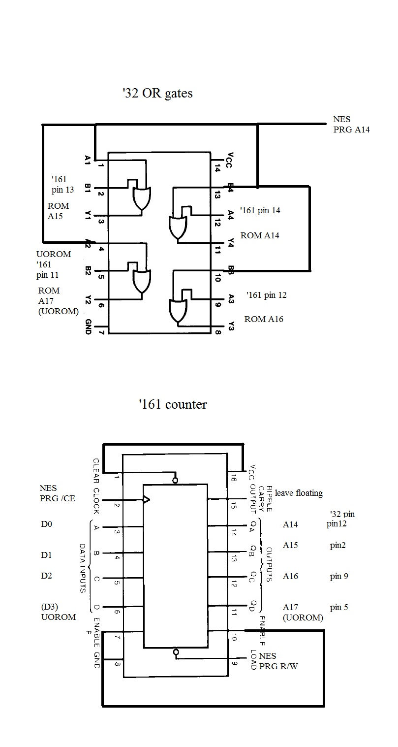
Image

I didn't draw all the interconnecting lines in there because it gets messy quick. I'll throw them in if the labeling doesn't make sense to you.

Hopefully that helps. If you want UNROM instead of UOROM just ground all the UOROM input pins and leave the outputs floating.

Not sure about the extra transitor what's it connected to?

The mirroring is basically just connecting CIRAM A10 to CHR A10 or A11. If CIRAM A10 is shorted to A10 (H bridge soldered) it's Vertical mirroring. If CIRAM is shorted to A11 (V bridge soldered) it's Horizontal mirroring. The labeling is kinda backward to what you'd think. But basically close the V if you want horizontal and vice versa. Contra is Vertical mirroring so CIRAM A10 is shorted to CHR A10.

by on (#83133)
FARID wrote:
This is Contra(U) for Famicom

Huh ?? Is this some kind of pirated cart or something ?

by on (#83139)
infiniteneslives wrote:
The labeling is kinda backward to what you'd think.

That's because the reverse engineered documentation uses a different terminology from the one used by Nintendo. Our documentation says which screens repeat, Nintendo says which ones don't.

by on (#83145)
Yep, we got it backwards. As the wiki puts it: "A horizontal arrangement of the nametables results in vertical mirroring [...] On cartridge boards made by Nintendo, this is selected by shorting the 'H' solder pad (for 'horizontal arrangement')." I guess that's why they call it "reverse" engineering :P

by on (#83183)
Please let me know about any kinds of mistakes :

Image

by on (#83245)
FARID wrote:
Please let me know about any kinds of mistakes :


I looked over the mapper chips quick and everything there looks good.

Just to make anyone aware that might be using this as a reference though: FARID changed up the pins compared to the standard wiring. It's all logically the same and will work fine, but things like which OR gate he chose to use for what signal are different. So I wouldn't use it as an exact reference for standard UNROM boards.

by on (#83260)
Quote:
FARID changed up the pins compared to the standard wiring. It's all logically the same and will work fine, but things like which OR gate he chose to use for what signal are different. So I wouldn't use it as an exact reference for standard UNROM boards


Thanks for your attention. Yes I changed some wiring to the pins of 74LS32. But you know this a a Clone not a real schematic as it is mentioned on the schematic.

Here is also PCB :

Front
Image

Back
Image

Here is PCB and Schematic layout files for proteus v7.7 SP2. If you want you can chagne it as you like.

by on (#83272)
Dang man, good contribution! I'm sure that'll come in handy to several folks around here.

by on (#83273)
Yeah, I'm pretty sure memblers also had made an custom UNROM board too, but this one is Famicom shaped instead of NES shaped.

BTW I wonder if it's possible to made new Famicom shaped game cases ?

by on (#83274)
qbradq wrote:
Dang man, good contribution! I'm sure that'll come in handy to several folks around here.


I wonder what is in your mind?! :idea:


Bregalad wrote:
BTW I wonder if it's possible to made new Famicom shaped game cases ?


New?! Do we really need a new case? This fits exactly to my old Famicom cases and I am pleased with it! :roll:

by on (#83276)
FARID wrote:
New?! Do we really need a new case? This fits exactly to my old Famicom cases and I am pleased with it! :roll:

I think that suggestion was for manufacturing new games from scratch without donor cases, much like the 72-pin case kits sold in RetroZone's NES Dev Tools section.

by on (#83278)
It's definitely possible to make cart plastics for the FC. It's just cost inhibitive to machine the mold for injection plastics unless you're making 100s-1000s of them.

I have aspirations to make cases for myself once I get my 3d printer together. They wouldn't be as pretty as injection molding, but more achievable and dirt cheap in small quantities. They'd still a lot better than slaughtering original carts for plastics.

by on (#83281)
Quote:
They wouldn't be as pretty as injection molding, but more achievable and dirt cheap in small quantities. They'd still a lot better than slaughtering original carts for plastics.

Well if it's for small quantities anyways, it won't make such a big change.

Oh and aren't 3D printers very expensive ? Maybe if you have one at your work anyways you could use it for stuff like that.

by on (#83285)
Bregalad wrote:
Oh and aren't 3D printers very expensive ? Maybe if you have one at your work anyways you could use it for stuff like that.


If you buy a complete turn key professional unit they are very expensive. I'm going to be building the reprap which is an open source design with most parts easily sourced. If I do EVERYTHING myself and stay away from kits I should Be able build it for under $400.

by on (#83287)
Capacitors are missing from that schematic, and sometimes that could be a major problem. Ideally you'd have a 4.7uF or 10uF cap where the power comes in to the board, and a 0.1uF cap near the power pins for every IC used. It would always be good to put that on the board, even if you don't plan on building the cart with them.

by on (#83304)
I can confirm what memblers says : Back when I was a begginer in electronics I didn't understand why one would put so many capacitor on the supply lines as many capacitors in parallel equals a big capacitor.

However, those are to compensate for the imperfection of the board, the lines resistance, inductance, cpacitance, etc.... If you don't put a capacitor near the power supply of the IC, the power supply will be noisy, and sometimes it can be so bad circuits stops to work altogether.
This is especially important if you work in higher frequencies, such as the 5Mhz the PPU uses for it's bus acesses.

by on (#83305)
Bregalad wrote:
I can confirm what memblers says : Back when I was a begginer in electronics I didn't understand why one would put so many capacitor on the supply lines as many capacitors in parallel equals a big capacitor.

However, those are to compensate for the imperfection of the board, the lines resistance, inductance, cpacitance, etc.... If you don't put a capacitor near the power supply of the IC, the power supply will be noisy, and sometimes it can be so bad circuits stops to work altogether.
This is especially important if you work in higher frequencies, such as the 5Mhz the PPU uses for it's bus acesses.


Yeah I had similar confusion at one point. Really it's all filtering, the issue is high frequency noise causing issues. So the capacitance has to be low to short out the high freq noise to ground (filter). Big caps are used more as a "reserve" to help maintain voltage. Both big and small caps are helping to maintain smooth power supply to the IC in different manners.

by on (#83318)
I don't think that Nintendo-made boards had a capacitor for each chip, though... what gives?

by on (#83320)
tokumaru wrote:
I don't think that Nintendo-made boards had a capacitor for each chip, though... what gives?


Usually it's 1 capcitor for every 2 chips on Nintendo boards. It's enough and cheaper than 1 per chip...

by on (#83324)
Here's what I said before about decoupling caps.

by on (#83325)
tokumaru wrote:
I don't think that Nintendo-made boards had a capacitor for each chip, though... what gives?


Most games I own have 3 caps. One big 22uF and two smaller ones don't let those resistor color banded components fool you, they're caps. But yes every time I've tried they work just fine without any of them.

by on (#83326)
Even if a board works without the caps in your environment, it might not be as reliable in an electrically noisier environment. Consider that Nintendo was busy building a reputation for its products being so reliable they're Tonka Tough (see TV Tropes article), especially after the recall of the first run of the Famicom.