Ok, so I sat down with LTspice and made some graphs. They're all huge numbers of pixels but trivial number of bytes, so I'm providing links rather than uploading them to the forum. (Is there a way to do this less stupid?)
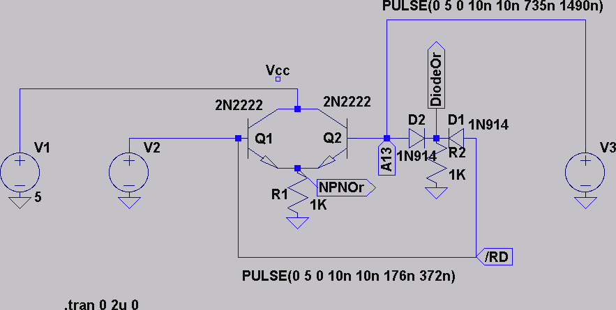
Here's the schematic I used to test it-
http://eamp.org/li/schematic.png [883x445]
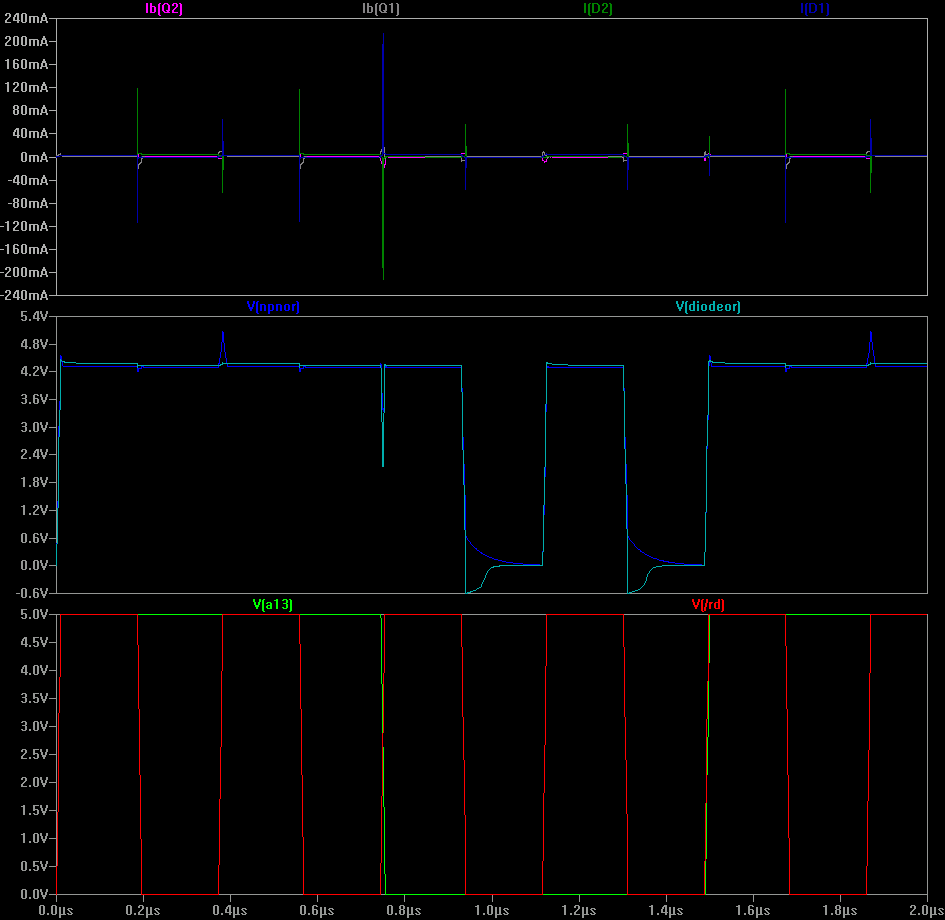
Here's a graph of ≈10 PPU pixels (starting with two nametable fetches)-
http://eamp.org/li/alltime.png [945x920]
The 1N914s (fairly standard signal diodes) have very large transient currents, even when (not shown) an ohm of resistance is put in series with the signal lines.
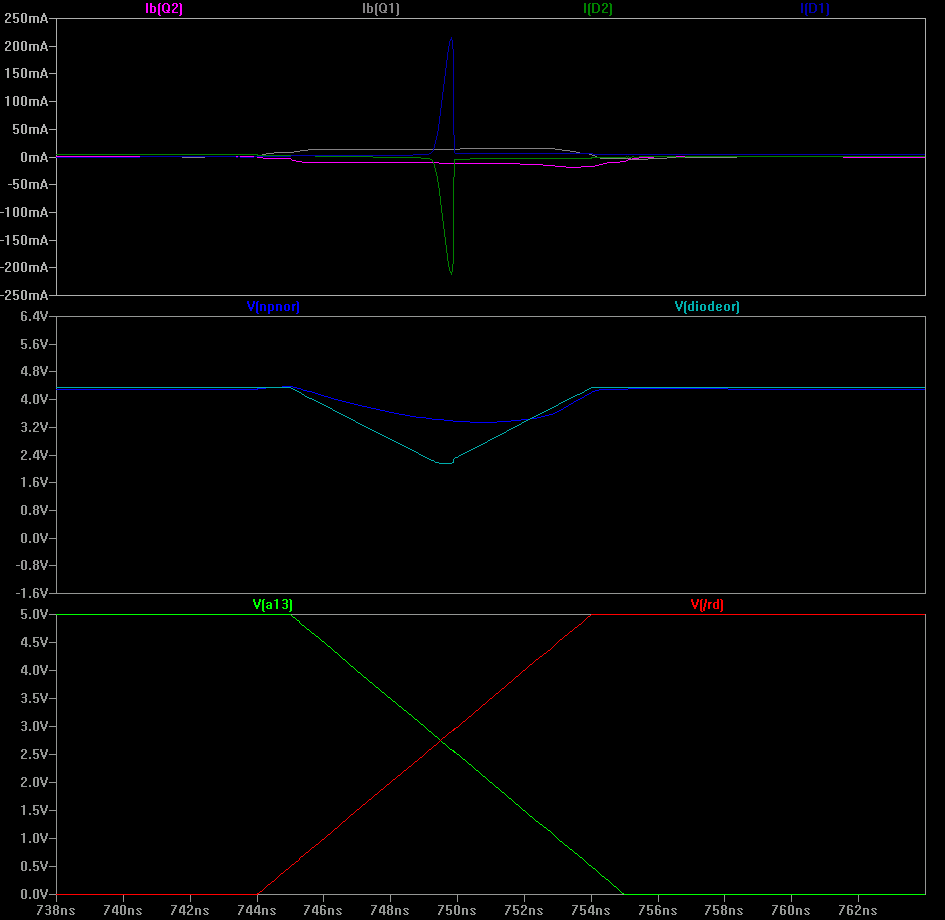
Here's a zoom of the moment when the PPU switches from nametable fetches to pattern table fetches-
http://eamp.org/li/crossover.png [945x920]
I assume a 10ns transition speed for the lines, without any evidence that that's true. It's a fairly standard assumption made with digital logic. If so, the diode OR here would fall below the "input low" voltage, and the output might glitch. That shouldn't matter—this happens during the start of the PPU's ALE signal, so the right value should win on the data bus moments later, but is bad for power consumption.
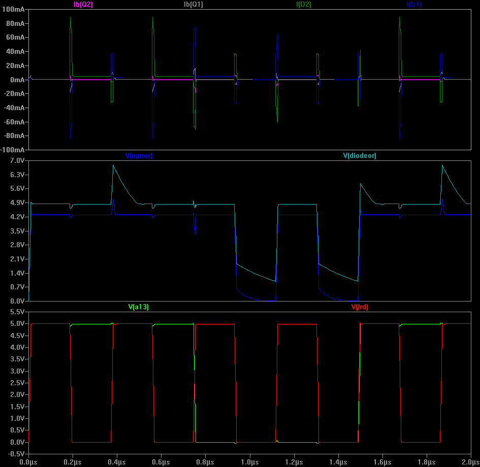
Here's a zoom of a successful read (A13 low, /RD low) -
http://eamp.org/li/bothtrue.png [945x920]
At 5mA, the 1N914s seem to capacitively couple (or is it inductive effects?) when forward biased, so there's undershoot when PPU /RD falls. Also, the BJTs pinch off current from the signal lines, so although current is drawn from /RD and A13 during the change, after the voltage across the resistor has risen, all the sustaining current comes from the voltage rail.
Finally, here's a trace of replacing the 1N914s with 1N5817s, the first Schottky diode that came up in the library provided with LTspice-
http://eamp.org/li/schottky.png [945x920]
That doesn't look very good. I have no idea if this is fair, however.
Regarding p-i-n diodes, LTspice doesn't have one in its library, so I was uncertain which one I should test with.
My conclusion: BJTs have clear advantages. It is probably unfair to use a 1kΩ resistor for the diode OR. Re-testing with a 10kΩ resistor provides a much saner graph, but still higher static power dissipation from the signal lines.
