Skip navigation
NintendoAge
Welcome, Guest! Please Login or Join
Loading...

NESRGB Top-loader w/custom back panel

May 23, 2015 at 7:05:26 PM
qwertymodo (5)

< Tourian Tourist >
Posts: 32 - Joined: 05/05/2015
Oregon
Profile
Awhile back, there was a thread on Assemblergames that resulted in 3-D printed SNES and Wii multi-out panels for the NES top-loader, which gave me the idea to try and make my own, with a few adjustments.  The main change I made was using a momentary tactile switch wired into a microcontroller as the palette switch, drastically reducing the size of the palette switch on the back panel and cleaning up the end result considerably.  I also tried getting it printed in a gray plastic rather than the white plastic they used, and I'm pretty happy with the result.  I'm using the Wii multi-out, because the Wii cables are far easier and cheaper to obtain, especially if you want component video.

The raised text looks better in person than it does in the photos, I couldn't get the camera to focus on the interior of the panel, it keeps focusing on the outer edge instead.

Currently, you have to choose one option out of S-Video, Component, or RGB, but the Wii pinout is supposed to support automatic switching between S-Video and Component in the NTSC pinout, or RGB and Component in the PAL pinout. I'm currently working on a signal switch to enable this behavior, but that's going to take awhile, so for now, it will only support one of the three options (it's just a matter of picking which one you wire up to those pins).  It will also support the stereo mod, with adjustments.

Palette switching is as simple as pressing the button.  If you want to save your selection so that it automatically loads that palette after a power cycle, just hold the button down for about half a second.  The cable header is a JST ZH-series header, giving a nice tight fit in a very small footprint.

Right now I'm waiting on one final (I hope) revision to the panel to come back that should fix a few minor issues I had with this one, but I'm posting the current version to gauge interest.


Edited: 05/30/2015 at 05:20 PM by qwertymodo

May 23, 2015 at 7:28:34 PM
Icelvlan88 (5)
avatar
< Little Mac >
Posts: 90 - Joined: 09/03/2013
Ontario
Profile
Very nice! How much do you think these will cost?


Edited: 05/23/2015 at 07:29 PM by Icelvlan88

May 23, 2015 at 7:45:11 PM
qwertymodo (5)

< Tourian Tourist >
Posts: 32 - Joined: 05/05/2015
Oregon
Profile
Haven't really decided yet. If I were to just straight-up sell the panels it would have to be the panel, PCB (populated and uC programmed), and a wiring harness. I need to look into whether or not I can buy pre-crimped wire lengths, because if not it'll get really old really fast crimping those wires. The other option would be to offer installations, including full NESRGB installs. I've been working on this in bits and pieces over the last few months, so I haven't sat down and actually worked out how much the cost and labor works out to for just a single install if I had all the parts in front of me all at once.

Jun 2, 2015 at 3:29:24 AM
RiverCityRansom2 (7)

< Eggplant Wizard >
Posts: 395 - Joined: 09/08/2011
United States
Profile
ahhh my friend fricking sweet PLEASE pm me or put me on a list if you decide to sell these or pre make em ready to go

Jun 2, 2015 at 9:26:42 AM
MODERATOR
Br81zad (97)
avatar
( Beck) < Bowser >
Posts: 7054 - Joined: 12/20/2012
Kentucky
Profile
Very nice work.

I'm interested

-------------------------


Jun 2, 2015 at 11:04:56 AM
Lincoln (138)
avatar
(Frank W. Doom) < Bowser >
Posts: 5976 - Joined: 12/19/2008
California
Profile
that looks,great. the wii port is a good idea.th

-------------------------
ebay auctionsrunning FS thread famiROM thread for .nes info and splitting / rom hacks link/discussion

Jun 8, 2015 at 3:00:12 PM
qwertymodo (5)

< Tourian Tourist >
Posts: 32 - Joined: 05/05/2015
Oregon
Profile
Well now I feel silly. I've tried 3 times to get the locking tabs lined up right, and it turns out that the whole problem was that I was measuring from one reference point, but modeling that measurement from a different reference point (inside vs outside measurements). Other than that, I'm happy with the last print I received. The multi-out port is nice and snug without being impossibly tight like the previous revision, or super loose like the one before that. I finally found my happy medium. I made the necessary adjustments, and I'm feeling really good about this being my final print (and I really hope it is, the costs start adding up after several consecutive revisions...). I also made a few slight modifications to the PCB and ordered a new run of those as well. I've designated this run as "rev A" and have marked both the panel and the PCB accordingly. Give it about 2-3 weeks for processing and shipping and I should have a final product.

Sadly, I blew up my toploader at some point, maybe a loose wire shorted something out, I don't know. I'm in the process of repairing and rebuilding it, so hopefully it will be back in working order by the time the new panel arrives.

Jun 11, 2015 at 11:49:51 PM
qwertymodo (5)

< Tourian Tourist >
Posts: 32 - Joined: 05/05/2015
Oregon
Profile
Woo, CPU swap has my toploader back up and running. It blew up while my SCART cables were in the mail, so today I got to see my toploader in all of its RGB glory for the very first time, and I must say it is gorgeous. Now it's back to working on the video switching circuit.

Jun 11, 2015 at 11:54:26 PM
AaronE (52)
avatar
(Aaron E) < El Ripper >
Posts: 1041 - Joined: 01/18/2013
Indiana
Profile
glad the CPU swap worked. I had a feeling that was the issue when you had mentioned it was heating up a ton.

Jun 11, 2015 at 11:59:55 PM
qwertymodo (5)

< Tourian Tourist >
Posts: 32 - Joined: 05/05/2015
Oregon
Profile
Yeah, it was pretty clear that the CPU was toast, I was just worried that there were other issues in addition to the CPU. If I had to guess, the toploader adapter board for the NESRGB puts a row of pins really close to the CPU pins, so I flush-cut all of those pins and then coated them in hot glue to insulate them against shorting out, in case that was the original cause.

Jun 14, 2015 at 1:38:10 AM
qwertymodo (5)

< Tourian Tourist >
Posts: 32 - Joined: 05/05/2015
Oregon
Profile
If anybody has ever worried about whether or not the extra regulator included with the NESRGB is really necessary, it isn't. At least not for the toploader. I haven't gotten a chance to measure on a front-loader. Toploader + NESRGB + component add-on board + my palette switch circuit + SMB + 1 dogbone controller = 390mA. I believe the original 7805 is rated for 1A, but I'm not sure. I replaced it with a 1.5A 7805 from TI, so even if you were to add a PowerPak to the load, it should still have plenty of overhead. It does get a bit warm, but it should still be well within the heatsink's capabilities, and to be fair, I never really checked how warm it got before installing the NESRGB.


Not sure what's going on with blue Mario, it doesn't seem to like the probes inline for some reason. Other than that it's still running regularly.

Jun 19, 2015 at 2:25:55 PM
qwertymodo (5)

< Tourian Tourist >
Posts: 32 - Joined: 05/05/2015
Oregon
Profile
So here's a question to anybody that's interested. It's pretty much done and ready to go, but one thing that I can still tweak a bit is the palette button. Specifically, the length of it. I have two options on actuator length. The current one I'm using sticks out a full 2.5mm from the outer edge of the panel. The next option down is about 3.5mm shorter, and as a result is actually recessed into the panel, and would require you to use a pencil or something to press it. However, using the shorter actuator, I also have the option of modifying the PCB to move it forward a bit so it sticks out however far I want, for more of a "happy medium". What do you guys think? Is there any preference on how far out the button should extend? I kind of feel like 2.5mm is more than I like, but personally I do like it to extend out rather than be recessed. Thoughts/opinions?

Attached photo is the current long version.


Edited: 06/19/2015 at 02:29 PM by qwertymodo

Jun 19, 2015 at 3:22:59 PM
SegF4ult (0)
avatar
(Xander ) < Little Mac >
Posts: 95 - Joined: 01/20/2013
Netherlands
Profile
If it were me personally, I would prefer the actuator to extend beyond the panel. The 2.5mm you've shown in the photo looks absolutely fine to me. Just my 2 cents

Jun 19, 2015 at 8:11:57 PM
qwertymodo (5)

< Tourian Tourist >
Posts: 32 - Joined: 05/05/2015
Oregon
Profile
Well, I have the latest print back in, with PCB, and I think I'm ready to call it production-ready. The switch length can still be adjusted, but it's not a huge deal. I think I've decided that as much as I like having the JST connector, crimping the cables is a real pain, so I'm not going to sell them with the connector or the cable if anybody wants to just buy the panel. If you want me to install it, I'll let it be up to the buyer whether or not they want it. The holes are a bit tight, but I'm using 26AWG and you can solder it straight into the holes just fine. Larger gauge might get a bit tight. I've been printing these using Shapeways' alumide material, which is their SLS printed material mixed with aluminum powder. There has been some concern expressed over the possibility of the aluminum powder causing shorts, but Shapeways claims (and I have verified with my own testing) that the material is not conductive. However, to address the concerns, I'll be selling them in the non-alumide SLS material as well, but they don't offer it in gray (hence the reason for going with alumide in the first place), so the non-alumide options are white or black. $45 plus shipping for a panel in white or black, $50 for alumide. I'll also offer installation services, but I'll have to figure out pricing on that.

Jul 29, 2015 at 1:56:42 PM
qwertymodo (5)

< Tourian Tourist >
Posts: 32 - Joined: 05/05/2015
Oregon
Profile
Ok, so I finally got around to working on the second half of this mod, the video switching circuit. The Wii multi out connector shares the same 3 pins for RGB, component, and S-Video, with the NTSC consoles getting S-Video and component, and PAL consoles getting RGB and component. There are two additional pins that are used to switch between the two options by shorting them together (i.e. NTSC unshorted = S-video, PAL unshorted = RGB, either region shorted = component). The shorting is done inside of the component cables themselves, which is why you can find composite + S-video cables, but never S-video + component. In order to support this functionality, I built an add-on board for the NESRGB that contains a component encoder and a video switching IC. My component encoder might need a little more tweaking to get the colors perfect, but I'm still happy with them (this is the "improved" palette)


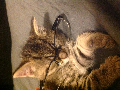
Here's what the board looks like mounted on the NESRGB. Ignore the riser wires, that was just to make it easier to remove while I'm prototyping, it will mount right onto the same pins as Tim's component encoder. Also, ignore the floating capacitors, I didn't have any of the chip tantalums that the board was designed for on hand. The physical switch selects between PAL and NTSC pinouts, so you can choose whether you want RGB or S-Video (you can't have both at the same time, unfortunately).


Jan 27 at 2:05:24 AM
qwertymodo (5)

< Tourian Tourist >
Posts: 32 - Joined: 05/05/2015
Oregon
Profile
I finally got around to digging up this old project and actually finishing it.  Nice, clean wiring harness makes installation really easy.  I can actually play my NES now  


Jan 27 at 7:56:02 AM
A2600 (17)
avatar
(Letter Carrier) < Meka Chicken >
Posts: 722 - Joined: 01/01/2011
Florida
Profile
Nice Job!

-------------------------
Ah, so you found the secret room, eh? Bask in the glory of a Mario Trilogy, a Pair of Zeldas and a Sextet of Megamans. Yes this is the little grey box that could and continues to do. What lies ahead is entirely up to you. YOU DECIDE

Aug 18 at 12:16:39 AM
X2Whiskey (0)

< Cherub >
Posts: 20 - Joined: 09/28/2016
Profile
Qwertymodo,

Fantastic looking board you have there! Would you be willing to share how you managed the auto switcher for the WII S-Video to Component output?

I have an NESRGB and component out board kit sitting here for a front loader and am really interested in using a WII output connector. I could just hard-wire it for component, but I'd rather future proof it for the down the road if it ends up in someone else's hands.

I also like Borti's RF/Power board replacement for the toploader and am thinking about designing one up similarly, but using the Wii connector. Perhaps I'm dreaming here, but an internal power supply would be awesome while I'm at it. Hey, one can dream!

Thanks!

Aug 20 at 3:53:54 AM
qwertymodo (5)

< Tourian Tourist >
Posts: 32 - Joined: 05/05/2015
Oregon
Profile
This does not use Tim's component video board, it replaces it entirely.  The auto switcher uses a TS5V330 with the switch controlled by pins 8 and 10 on the multi-out connector.  The switch pin is pulled up to Vcc with a resistor and then connected to one of the multi-out pins.  The other multi-out pin is connected to Gnd.  When the switch is high, the switch selects RGB, when it's low it selects component.

Aug 20 at 5:49:18 PM
X2Whiskey (0)

< Cherub >
Posts: 20 - Joined: 09/28/2016
Profile
Thanks for sharing!