NA,
I've spent many a night trying to find the proper way of doing this, as the eprom conversions on NESDEV were not working for this game. Numerous people have FFIII repros on sale for horrendous prices, so I thought I should make this topic, so 5 years from now, people can make their own game and be happy with what they made with their own two hands. Good Luck. I'll review and update soon with better pictures. This does work, as I've done it about 10 times already.
WARNING - Follow this at your own expense. It worked for me.
Required Parts:
(1) Super Mario Bros 2 Cart
(1) 27C4001 (or similar) eprom
(2) N4148 Diodes
(1) Battery from another game, or a battery holder from Radio Shack)
(1) 10 ohm Resistor
(1) 2.2uF 16v Capacitor
(1) CXK5864APS-12LL CHR-RAM
I pulled alot of these parts from a TKROM based game.
Choosing your Cart:
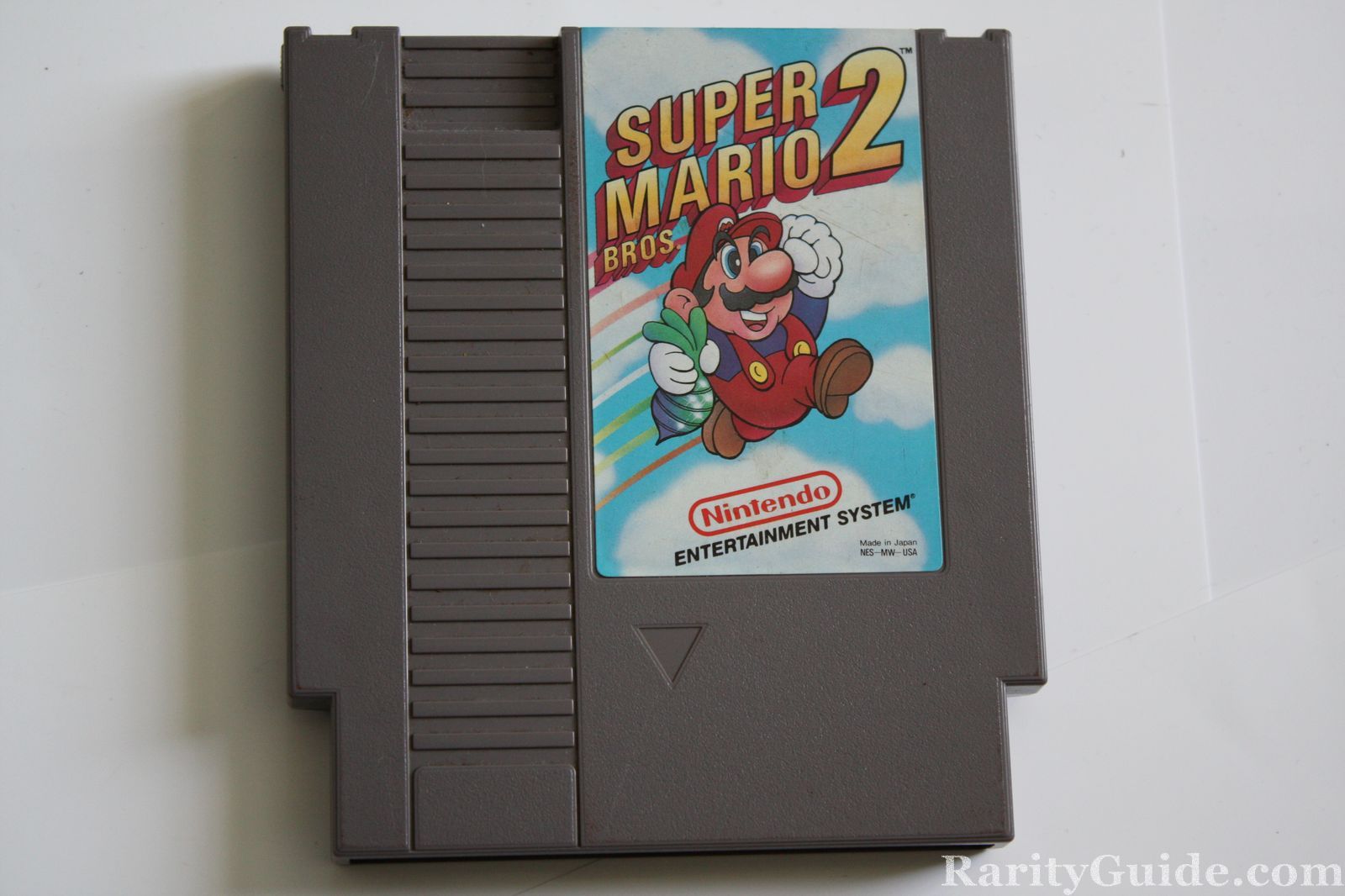
You must choose the Super Marios Bros 2, that does not have the seal.
NOTE: Some people do remove the "rare" board from inside and replace it with the other REV of the board. Beware.
Choosing your Eprom:
Verify your eprom burner can burn M27C4001 , or 27C4001 eproms (similar pin layout). I use a simple USB Top853 to do my NES games.
Burning the Eprom:
This guide assumes you know how to split a rom image and burn an Eprom properly for a NES repro.
Choosing the CHR-RAM:
Choose a CXK5864APS-12LL (See Bootgod web site for games that have this)
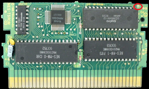
 Setting up the PCB:
On the Super Mario Bros 2 Board, desolder the PRG and the CHR chip.
How to Solder PRG:
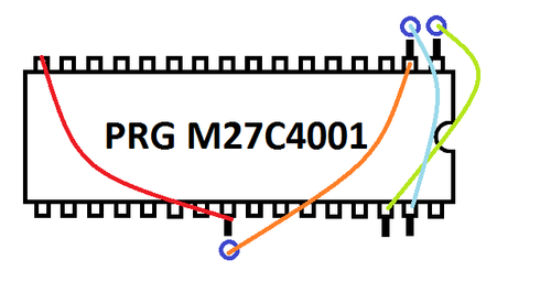
PRG socket: (NESDev)
Bend up pins 1, 2, 24, 30 and 31 (or cut tracks 2, 24, 30 and 31)
Solder pin 2 to hole 24 (A16)
Solder pin 24 to GND (OE)
Solder pin 30 to hole 1 (A17)
Solder pin 31 to hole 2 (A18)
How to Solder CHR-RAM:
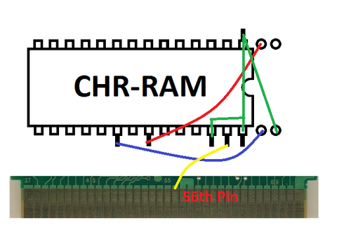
(Remeber this is a 28 pin CHR-RAM on a 32 pin area, so pin 1 of the RAM should be set in socket 3 on the board)
Bent up Pins 1, 20, 22,26,27 and 28
Solder pin 22 to hole 2 (on socket not your chip's hole)
Solder pin 20 to hole 31
Solder pin 26 to pin 28, then a wire from pin 28 to pin 1. After that solder a wire from pin 1 to hole 32 on the board.
Solder pin 27 to the 56th pin on the back of the PCB for CHR-RAM functions.
Alternative Layout for CHR-RAM for (From Lincoln)
Using a CXK5864PN-15LL
pin 20 (/CE1) -> hole 31
pin 22 (/OE) -> hole 2
pin 26 (CE2) -> hole 32 (5v)
pin 27 (R/W) -> cart 56
i left pin 28 (Vcc) down as hole 30 is 5v.
i bent pin 1 up and left it unconnected, but I'm pretty sure it would be fine down as it is NC.
Battery:
The symbols in this diagram are similar to what you'll see on the board, especially where the Capacitor connects (negative side).
Also I used a 2.2uF 50v Capacitor, instead of a 16v