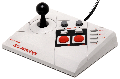
I plan on converting my Emio Edge joystick to work with NES/AVS. The Emio Edge joystick, despite criticisms that the joystick does not actually function properly with an NES Classic Mini, seems incredibly well made, containing a JLF cloned joystick and real snap in 30mm arcade buttons. As a bonus, after I'm done, I'll have a nice long 9 foot cable left over to use as an upgrade for the official NES Classic Mini gamepad.

My plan is to restore this joystick to work with original hardware by recycling the switches and arcade parts by connecting them to a breakout breadboard with an NES Advantage schematic on it. The original PCB will remain in place for structurual support, however the switches present on the PCB will be isolated by cutting the traces, and wires will be soldered directly to the pots and switches on the solder side of the PCB. I plan on using a Gamerz Tech NES clone controller for the cord as it has the little grommet that should fit the joystick. No original NES Advantage or OEM NES controllers will be butchered...
I spent the better half of last night mapping out the traces on the turbo circuit on the original NES Advantage and have determined that the NES Advantage uses a 74xx04 series Hex Inverter to create three relaxation RC oscillators.

That's only two logic chips for the NES Schematic and seems fairly simple to do. I calculated the approximate frequency of these oscillators (without actually measuring the frequency range while plugged in) and concluded that the A/B turbo should output an approximate frequency range from 4.35Hz - 31.56Hz and the slow motion turbo would output about 23.67Hz. However the exact frequency of a relaxation oscillator is dependant upon the exact voltage level the logic gate inputs go high, and the textbook formula [Time = 2.2 * R * C] assumes a crossover voltage of 1/2 VCC. There is a lot of variance even among chips of the same type so these calculations could be highly inaccurate compared to real world results. Later on, I will test the actual frequency on my multimeter while plugged into an NES to determine the exact range for determining component values for the final schematic.
There are however a couple of differences between the original NES Advantage and the Edge joystick make full replication of all of the NES Advantage functions a bit troublesome. For starters, the Edge joystick uses a custom ASIC glop top that is useless for modding. Prior to tracing the NES Advantage PCB, I was planning on using a low current 556 (dual 555 timer) for the A/B turbo oscillators, which would produce a more stable signal. The textbook schematic for astable operation creates non-50% duty cycle (reducing the size of R1 will make duty cycle closer to 50), but this can be solved by eliminating R1 and utilizing the output for feedback to produce a true 50% duty cycle square waveform.
Despite the limited utility of a Slo-Mo circuit, I think it would be beneficial to have one for completionist sake. This would necessitate an third oscillator (555 timer) requiring an additional logic chip and potentially larger breadboard. At this point I may as well revert to using a 74xx04 chip for the oscillators since it can facilitate three oscillators instead of just two. If I decide to build a relaxation oscillator with a hex inverter, do I need to use 74HC04 or 74LS04? I hear it makes a difference which chip type you use when interfacing non-digital signals.
A bigger issue is that the Slow motion switch on the Edge joystick appears to be a DPDT momentary pushbutton type rather than the push-on-push-off type switch like those used for the A/B turbos. As I do not have a part number for this switch, I am unsure if I would be able to source a replacement. Using the stock momentary pushbutton switch to toggle slow motion would require adding a flip-flop (extra chip) filter circuitry to adequately de-bounce the input, a second filter circuit to bias the flip flop during power up (so that the controller does not initiate with the "slow" setting activated), and additional logic (extra chip) to combine the oscillator output with the flip-flop output. So either I omit the slow motion feature altogether, or add a bunch of chips, or find a suitable replacement push-push swith with the exact height and pin spacing of the momentary switch I'm replacing.
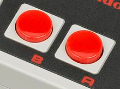
Lastly, the Emio Edge joystick has removed the mostly useless Player 1 / Player 2 select switch and added an equaly useless "A+B" momentary button to the joystick. Why anyone would need a dedicated "A+B" button when they can actuate A and B simultaneously or independantly with two fingers is beyond me. But anyway, for better or worse, the "A+B" button exists so I need to find an alternative function for it. One potential use I have cooked up is to use this to call up the AVS menu by actuating "A+B+Select". I really like the idea of adding such a hidden feature, but this also requires additional logic to use. The button inputs are normally high, active low, so I could potentially tie in this signal to three inputs using a 74xx08 quad AND two input gate. But this is not without disadvantage, as it adds an extra chip (I need to minimize the chip count to ensure I have enough space to install the breadboard) and accidentally hitting the AVS menu button during gameplay would effectively reset the game.
If I stick to K.I.S.S. design principal (Keep It Simple Stupid), I could just have these two rarely used buttons do nothing at all or simply mirror Start+Select. This would leave me with a compact breadboard with only two chips (a 556 and a CD4021).