Skip navigation
NintendoAge
Welcome, Guest! Please Login or Join
Loading...

Dragon Quest 3 English Reproduction More wires than ever before!

Sep 9, 2014 at 6:59:32 PM
MrPete1985 (43)
avatar
< El Ripper >
Posts: 1221 - Joined: 07/13/2014
Pennsylvania
Profile
Here is how you make a DQ3 repro that saves.  You Need:
A HiROM PCB
1 32mbit TSOP
1 16mbit TSOP
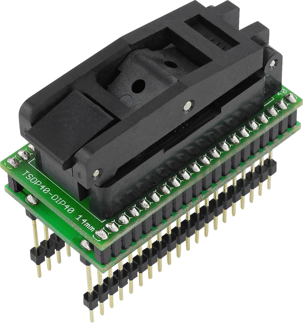
2 TSOP to DIP boards
1 139 memory decoder
All your basic soldering stuff

To start off I programmed both my TSOP chips and tested them with this board I made
http://nintendoage.com/forum/mess...
After the test I knew that both TSOP chips were programmed correctly.

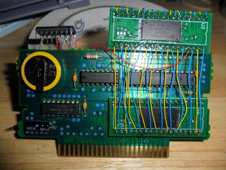
Next I soldered the 32mbit chip into the PCB, my desoldering iron sucks so I ran wires between every point on both chips except for the /OE pin.

Next I cut the trace that goes from the /OE pad on the PCB to the MAD-1 chip


Once I had the trace cut and both TSOPs connected it is time to wire them into the 139


Here is the completed board
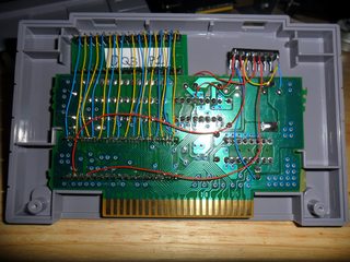


And yes it saves. 

-------------------------
Just about anything you would want to know about SNES repros
The best SNES PCBs you can buy
Mask ROM Adapter Boards
Fixing stuff on my YouTube channel

I fix game cartridges and make repros.  Send a PM If you are interested in my services.


Edited: 10/29/2017 at 12:01 PM by MrPete1985

Sep 9, 2014 at 9:48:26 PM
MarkFrisbie (5)
This user has been banned -- click for more information.
(Mark Frisbie) < Little Mac >
Posts: 73 - Joined: 01/26/2013
United States
Profile
Nice work! On a HiRom cartridge, EPROM pin 35 is really "A23", not A22. On a low rom cart, because the addresses are shifted by 1 above A14, then it would be A22.
Also, you should ground your inputs on the other side of the decoder.


Edited: 09/09/2014 at 09:51 PM by MarkFrisbie

Sep 9, 2014 at 10:45:03 PM
MrPete1985 (43)
avatar
< El Ripper >
Posts: 1221 - Joined: 07/13/2014
Pennsylvania
Profile
Originally posted by: MarkFrisbie

Nice work! On a HiRom cartridge, EPROM pin 35 is really "A23", not A22. On a low rom cart, because the addresses are shifted by 1 above A14, then it would be A22.
Also, you should ground your inputs on the other side of the decoder.


Didn't know about the address shifting, all the pinout I have seen show it as A22.  Changed the picture to say pin 35.

Also any reason reason to ground out the 2 inputs on the other side?  The data sheet says it is 2 independant decoders on one chip, I have used a 139 to use more than a single 27C801 before and left them floating without any issues.

-------------------------
Just about anything you would want to know about SNES repros
The best SNES PCBs you can buy
Mask ROM Adapter Boards
Fixing stuff on my YouTube channel

I fix game cartridges and make repros.  Send a PM If you are interested in my services.

Sep 9, 2014 at 10:58:38 PM
MarkFrisbie (5)
This user has been banned -- click for more information.
(Mark Frisbie) < Little Mac >
Posts: 73 - Joined: 01/26/2013
United States
Profile
Even though you aren't using that side, it's good practice to not have the inputs floating. The data sheets usually recommend you ground the inputs. It's about conserving power too.  You wouldn't notice any performance issues.  It's just good electronics practice.  

oh, and your wiring of the 139 is exactly correct too which is why it does indeed save.


Edited: 09/09/2014 at 11:02 PM by MarkFrisbie

Sep 11, 2014 at 5:14:19 PM
galvatryne (119)
avatar
(david desgagne) < El Ripper >
Posts: 1317 - Joined: 03/17/2010
Quebec
Profile
thanks for sharing man!

Sep 12, 2014 at 5:55:56 AM
josete2k (7)

(Jose Ruiz) < Eggplant Wizard >
Posts: 251 - Joined: 09/01/2012
Spain
Profile
Maskrom pin 35 is always A22 even in HiRom or LoRom, the difference is the slot pin they are wired to.

The 139 is a dual decoder, so if you're not using the second decoder you don't need to wire its inputs. This is because the active or enable pin is turned on when you have it at low level (L, 0 or GND), if it's floating or at Vcc the decoder is disabled.


Edited: 09/12/2014 at 06:08 AM by josete2k

Nov 19, 2014 at 3:35:20 AM
niffel (0)

< Cherub >
Posts: 16 - Joined: 11/18/2014
Germany
Profile
Hi,
is it possible to build a 64mbit card with this setup? When I change the 16mbit with 32mbit?
It is an expanded rom wich I need to get running.

Nov 19, 2014 at 5:50:04 AM
MrPete1985 (43)
avatar
< El Ripper >
Posts: 1221 - Joined: 07/13/2014
Pennsylvania
Profile
Should work, what game are you planning to make? Didn't know there were games bigger than 48mbit other than Star Ocean hack.

-------------------------
Just about anything you would want to know about SNES repros
The best SNES PCBs you can buy
Mask ROM Adapter Boards
Fixing stuff on my YouTube channel

I fix game cartridges and make repros.  Send a PM If you are interested in my services.

Nov 19, 2014 at 6:37:39 AM
niffel (0)

< Cherub >
Posts: 16 - Joined: 11/18/2014
Germany
Profile
There where 2 new translations released as final versions this month. (Bahamut Lagoon and FinalFantasy 5 in german)
They expanded the rom to 64mbit to make reproers life harder.
I would like to have those two in my collection. Espacially FF5!

When I have for example an BJ3M board, do I need the 139 as mem controller?
BJ3M has already 2  36pin slots. Is rewiring the Mad1 enough in this case? Or does this give me those save issues I heard from?

Nov 19, 2014 at 7:53:47 AM
MrPete1985 (43)
avatar
< El Ripper >
Posts: 1221 - Joined: 07/13/2014
Pennsylvania
Profile
Never used a BJ3M board, check the ROMs with ucon64 they may be padded and not need the second chip like Return to Dinosaur Land.

-------------------------
Just about anything you would want to know about SNES repros
The best SNES PCBs you can buy
Mask ROM Adapter Boards
Fixing stuff on my YouTube channel

I fix game cartridges and make repros.  Send a PM If you are interested in my services.

Nov 19, 2014 at 8:01:23 AM
niffel (0)

< Cherub >
Posts: 16 - Joined: 11/18/2014
Germany
Profile
I checked it already.
There are padded, but only with 1.5 MB. And when I look into the rom with SNES-Edit or a Hex-Editor there are some pointer tables and other stuff in the very end of the Rom...
In the readme is written, that this has been done to make it harder to repro those translations.
I will give it a try and when it works I will post it here.

Nov 19, 2014 at 10:20:34 AM
MrPete1985 (43)
avatar
< El Ripper >
Posts: 1221 - Joined: 07/13/2014
Pennsylvania
Profile
I would try it like I have done dragon quest 3 just use 2 32mbit chips and it should work.

-------------------------
Just about anything you would want to know about SNES repros
The best SNES PCBs you can buy
Mask ROM Adapter Boards
Fixing stuff on my YouTube channel

I fix game cartridges and make repros.  Send a PM If you are interested in my services.

Apr 9, 2015 at 4:09:30 AM
niffel (0)

< Cherub >
Posts: 16 - Joined: 11/18/2014
Germany
Profile
Hi there,

now i found the time to build me a testing pcb with your wireing of the 139.
I used a BJ5M board. Those have two 36 pin masksrom slots. This way I dont need so much wireing.
I wanted to let you know, that it works great. With 48 AND 64 mbit roms!!

Thank you for sharing your build up.

Apr 30, 2015 at 6:21:43 PM
Omega-Red (0)

< Cherub >
Posts: 5 - Joined: 03/30/2015
Profile
Originally posted by: niffel

Hi there,

now i found the time to build me a testing pcb with your wireing of the 139.
I used a BJ5M board. Those have two 36 pin masksrom slots. This way I dont need so much wireing.
I wanted to let you know, that it works great. With 48 AND 64 mbit roms!!

Thank you for sharing your build up.
I thought BJ3M and BJ5M are meant for 2x 16MBit max. What would I have to rewire? ;-) Got tons of BJ3M PCBs.


Edited: 05/03/2015 at 06:41 AM by Omega-Red

May 2, 2015 at 7:20:59 PM
VirtualAndy (1)
avatar
< Little Mac >
Posts: 96 - Joined: 07/10/2013
Ontario
Profile
I'm not even familiar with the BJ5M board, what games utilize this PCB?

May 3, 2015 at 6:44:17 AM
Omega-Red (0)

< Cherub >
Posts: 5 - Joined: 03/30/2015
Profile
Originally posted by: VirtualAndy

I'm not even familiar with the BJ5M board, what games utilize this PCB?

:-) I've never seen one before and it's also not listed on snes central. But it would be a BJ3M with bigger SRAM...
Might be an early SimCity 2000 or so.


Edited: 05/03/2015 at 06:46 AM by Omega-Red

May 4, 2015 at 11:20:27 AM
Moothead2 (2)

(Jordan ) < Eggplant Wizard >
Posts: 364 - Joined: 04/15/2012
United Kingdom
Profile
If you plan on making one of these you can make it much cleaner by soldering the second board to the back on the main board like so:


The above image is from a Tales of Phantasia Repro but the same techniques works with this too. I've had one working that way before so I can confirm it works.


Edited: 05/04/2015 at 11:21 AM by Moothead2

May 9, 2015 at 9:25:00 AM
niffel (0)

< Cherub >
Posts: 16 - Joined: 11/18/2014
Germany
Profile
@ OmageRed and VitualAndy
   The BJ5M I found in Sangokushi IV and Winning Post 2 :-)  Same layout as BJ3M - only more SRam.

@ Moothead2
   Soldering the second chip directly on the back is a good practice. But I dont have an adapter to programm my tsop chips directly. This way i would have to desolder the pins after programming :-(  

If anyone knows a cheap adapter for tsop 40 chips for an gq-4x  let me know ;-)

@ OmeageRed (I think I know you from SNESProjects :-), here is the wireing for an 64mbit game on a BJ3M/BJ5M PCB that saves (those pictures are from the new german translation of Bahamut lagoon and it works without problems)


Edited: 05/09/2015 at 09:26 AM by niffel

May 9, 2015 at 12:55:16 PM
josete2k (7)

(Jose Ruiz) < Eggplant Wizard >
Posts: 251 - Joined: 09/01/2012
Spain
Profile
Originally posted by: niffel


@ Moothead2
   Soldering the second chip directly on the back is a good practice. But I dont have an adapter to programm my tsop chips directly. This way i would have to desolder the pins after programming :-(  
If anyone knows a cheap adapter for tsop 40 chips for an gq-4x let me know ;-)


http://www.buyicnow.com/bp.php?i=...


Edited: 05/09/2015 at 12:56 PM by josete2k

May 12, 2015 at 2:47:42 AM
niffel (0)

< Cherub >
Posts: 16 - Joined: 11/18/2014
Germany
Profile
Thanks for the link Josete2k, but I have allready one of these.
This way I would need to desolder the pins after Programming.

I meant something like this:


But these are very expensiv (170 USD for the one in the picture )


Edited: 05/12/2015 at 02:48 AM by niffel

May 12, 2015 at 7:39:55 AM
mrTentacle (0)

< Cherub >
Posts: 18 - Joined: 07/25/2014
Profile
Hi all, long time lurker here.
Niffel, wouldn't it be possible to build a programming adapter with cheap pogo pins and program the chips soldered to the adapter board without the headerpins? Like these: https://www.sparkfun.com/products...

-------------------------
I sell on Tindie


Edited: 05/12/2015 at 01:36 PM by mrTentacle

May 19, 2015 at 5:18:27 PM
Omega-Red (0)

< Cherub >
Posts: 5 - Joined: 03/30/2015
Profile
Originally posted by: niffel

Thanks for the link Josete2k, but I have allready one of these.
This way I would need to desolder the pins after Programming.

I meant something like this:


But these are very expensiv (170 USD for the one in the picture )

1st... Thank you!
2nd... Yes, I'm at snes-projects too... :-)

Like my TL866 adaptor


over at snes-projects is compatible to the gq-4x, all programming adaptors are. You can get them for about 40 bucks.

http://www.ebay.de/itm/TSOP32-TSO...

;-)

Look...


Edited: 05/20/2015 at 12:27 PM by Omega-Red

Dec 21, 2016 at 10:17:06 AM
X2Whiskey (0)

< Cherub >
Posts: 20 - Joined: 09/28/2016
Profile
I'd like to make a Star Ocean repro without the DSP-1 chip. There's a IPS that puts the ROM at 96 Mb.

Can I follow the procedure in the OP with the addition of wiring /OE of the 3rd 32Mb TSOP to pin 6 (1Y2) of the 139?

May 11, 2017 at 1:07:24 PM
Ice Man (22)

< Meka Chicken >
Posts: 548 - Joined: 05/13/2016
Germany
Profile
Sorry to bump such an old topic but this is the best place my problem fits in.
I was making a Bahamut Lagoon (ExHIROM) German translation cart on a SHVC-1J3M using a MX29LV640 IC.
While the game works fine and can be dumped properly it fails to save.

The MX29LV640 operates in BYTE mode.
D0-D7 are going to D0-D7 SNES
D8-D14 are ignored.
D15 goes to A0 SNES
A0 goes to A1 SNES
...
A21 goes to A22 SNES
/CE goes to /CE SNES
/OE to Mad-1 Pin 4
VCC, WP#ACC, RESET, WE are connected to 3.3V via AMS1117 3.3V
BYTE goes to GND

I tried changing MAD-1 Pin 13 and 12 to A23 / A22 like it was in Tales of Phantasia. No success.
Even tried A22/A23. Same result.
Game works but fails to read/write saves.
With an additional 74LS139 the game won't boot.

I have already successfully made the game using 2x29F033 + 74LS139.

Anyone know a solution for MX29LV640?


Edited: 05/11/2017 at 01:08 PM by Ice Man

May 11, 2017 at 3:50:54 PM
Baby_rose (0)
avatar
(Kat Susanne ) < Tourian Tourist >
Posts: 32 - Joined: 06/08/2015
Louisiana
Profile
Did you put caps on your regulator so the voltage output will be stable?