Skip navigation
NintendoAge
Welcome, Guest! Please Login or Join
Loading...

Reproduction New Method for Making English Star Ocean out of a Donor Compatible with SNES Mini

Nov 15, 2015 at 6:59:37 PM
MrPete1985 (43)
avatar
< El Ripper >
Posts: 1221 - Joined: 07/13/2014
Pennsylvania
Profile
So I'm sure everyone knows about the old method make an English Star Ocean out of a donor cart by replacing a single ROM on the board.

http://www.mmmonkey.co.uk/star-oc...

This is all well and good but because you have 1 ROM operating 5v and another at 3.3v the game will crash during the opening cutscene on a SNES Mini.

Just to be clear this is not the best option to make an English Star Ocean because the you are operating a 3.3v chip with 5v logic.  I suggest using a PCB from ArcadeMaster1 or RetroStage because the board will operate entirly at 5v.

But if you want to use the Japanese as a donor for some reason, maybe you just like the SFC shell better and don't want to have to reprint a label here is a method I came up with that will work on a SNES Mini using a single EEPROM

What you will need:
All your basic soldering gear
A Japanese Star Ocean
A MX26L6420 EEPROM
A low dropout 3.3v regulator
A 0.1uf capacitor for the vreg
Some software that I will cover below

Start off with a translated ROM, open it with SNESx9 to make sure it plays correctly before going any further


Next check your ROM for a copier header and remove it if it has one


Now we will need to pad the ROM to fill the whole 64mbit EEPROM.  We will need to split the ROM then double up the second half

Load up a Hex editor, I use HxD.  Click on "Extras" then select "Split..."


Now set the output path and set it to split the ROM at 4MB


Now you will have 2 files, the first half is 4MB and the second half is 2MB


Now open the command prompt, hold shift and right click while no file is selected and select "Open command window here"


Next use the copy command with the binary flag to double up the second half (top command) then combine the first half and the padded second half into a single file (Bottom command)


Now you will have a single 8MB file that will fill the whole EEPROM, ready to program to your EEPROM


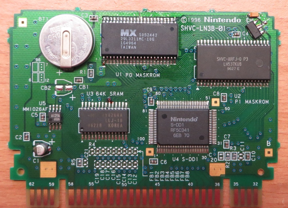
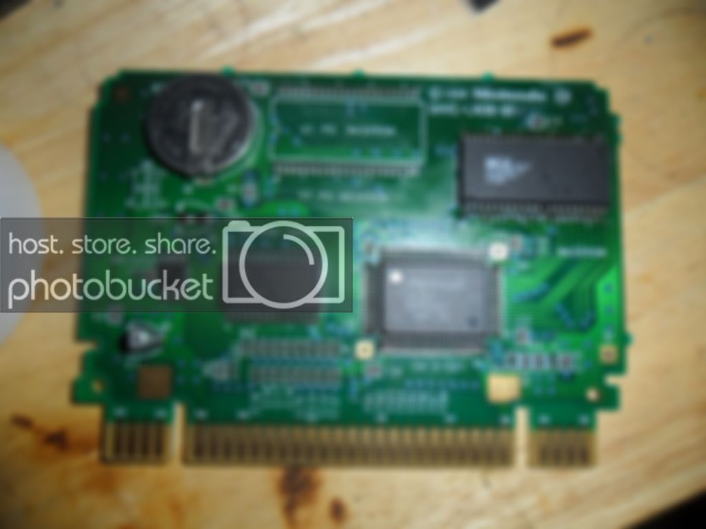
After programming your EEPROM it is time to get the board ready, here is a stock board


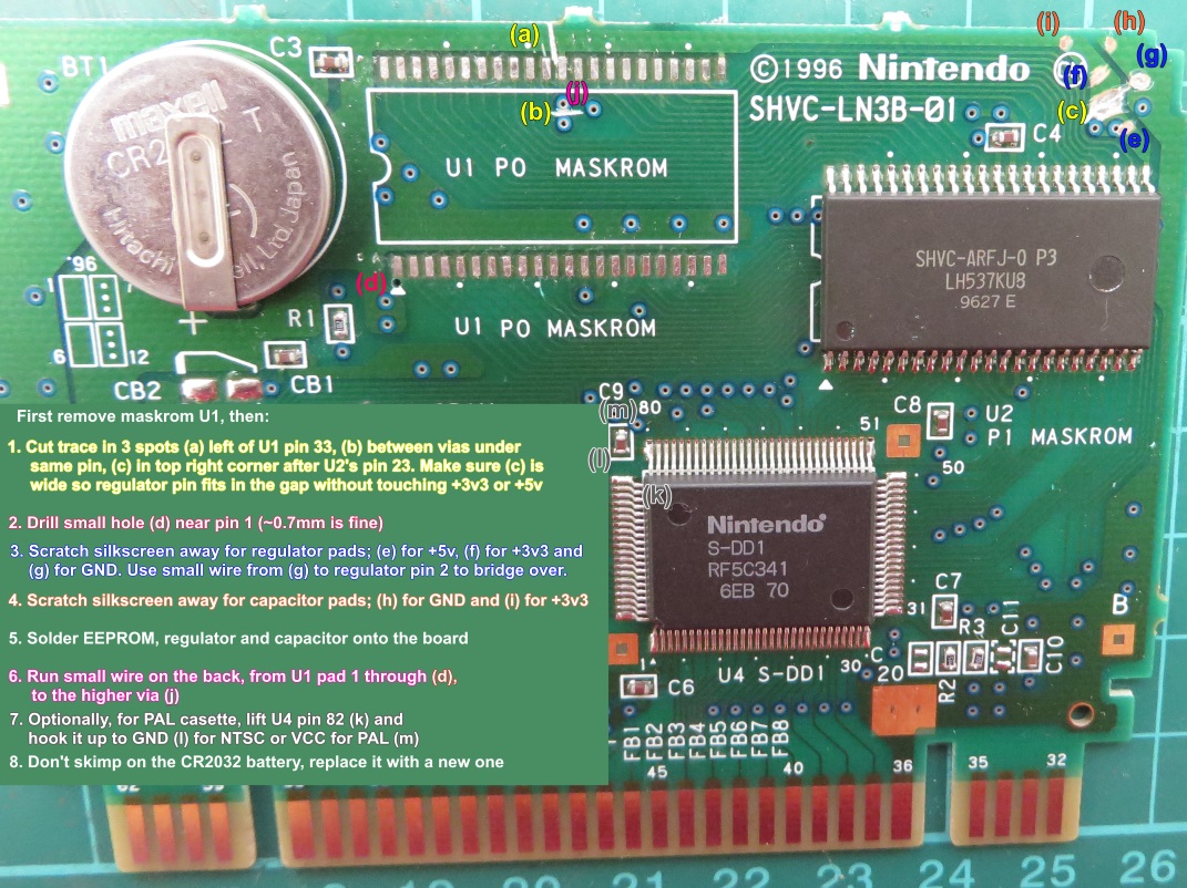
Start off by removing both of the Mask ROMs, I use a hot air station


Next I put some flux on the pad then heat them up with my hot air station again to level out the pads


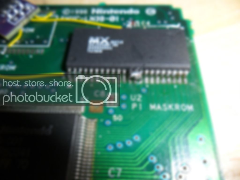
Now it is time to get the EEPROM ready, bend up A21(pin 1), /CE(pin 12), VCC(pin 23), and /WE(pin 33)


Now solder the EEPROM into the spot on the right making sure the lifted pins are not touching the pads


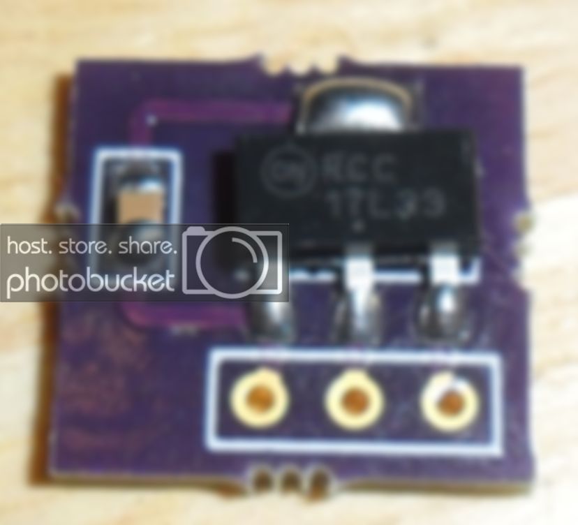
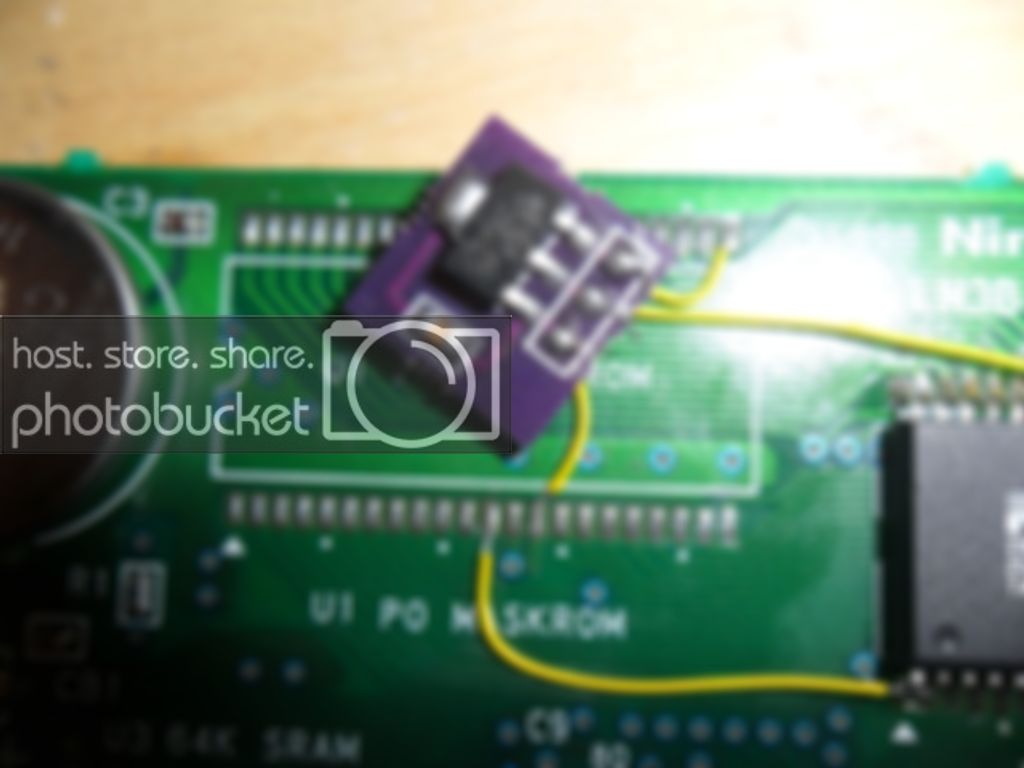
Now start wiring the vreg, I made up some PCBs because I did not like mounting it strait to the board


Start off by connecting the /CE pin to ground, the pin to the right is a ground pin so I just used a glob of solder


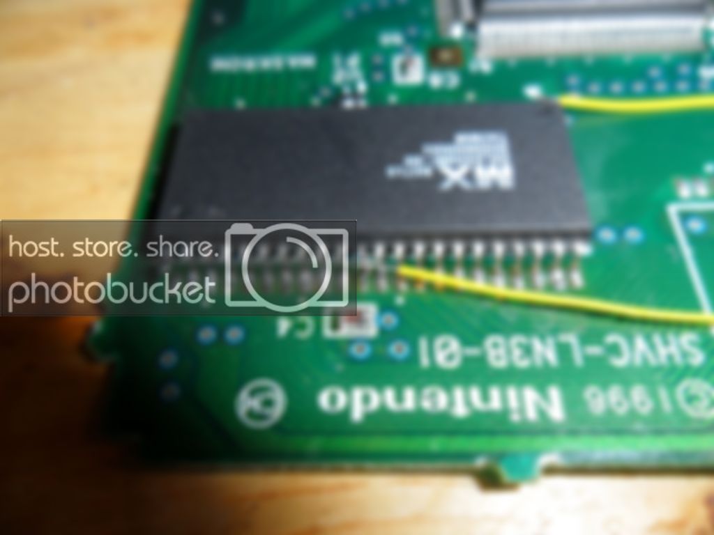
Now connect the VCC and /WE pins to the 3.3v output of the vreg, I just stripped a long wire and soldered it to the 2 lifted pins


Now conenct the Ground and 5v input on the vreg


Now connect a wire from A21 on the EEPROM to the /CE pad for the left ROM


And an overview of the completed board


Now some technical info on how exactly this method works.  The S-DD1 chips controls what ROM is active by switching the /CE lines to either VCC or Ground, when /CE is conencted to ground that chip is active.  by hard wiring the EEPROM /CE pin to ground the chip is always active.  By manually controlling A21 on the EPROM we can select the upper or lower half of the EEPROM.  A21 is connected to the /CE line on the left ROM line so this way when the S-DD1 enables the first ROM A21 will be pulled low and only the first half of the chip is enabled.  And when the S-DD1 disables the first ROM A21 will be pulled high and only the second half of the chip will be enabled so it is basically 1 ROM acting as 2.

I was able to play this board on my SNES Mini for over an hour without any crashes and saving still works.

-------------------------
Just about anything you would want to know about SNES repros
The best SNES PCBs you can buy
Mask ROM Adapter Boards
Fixing stuff on my YouTube channel

I fix game cartridges and make repros.  Send a PM If you are interested in my services.


Edited: 11/15/2015 at 07:04 PM by MrPete1985

Nov 17, 2015 at 3:17:13 AM
josete2k (7)

(Jose Ruiz) < Eggplant Wizard >
Posts: 251 - Joined: 09/01/2012
Spain
Profile
Nice, what kind of capacitor are you using with the regulator?


It seems 0.1uF ceramic and as is described in the datasheet that's not the correct one, you need 22uF tantalum.


Edited: 11/17/2015 at 03:20 AM by josete2k

Nov 17, 2015 at 4:43:40 PM
MrPete1985 (43)
avatar
< El Ripper >
Posts: 1221 - Joined: 07/13/2014
Pennsylvania
Profile
Yea that's what I used, I'll have to double check my datasheet. Like I said this is not the ideal way to build a Star Ocean

-------------------------
Just about anything you would want to know about SNES repros
The best SNES PCBs you can buy
Mask ROM Adapter Boards
Fixing stuff on my YouTube channel

I fix game cartridges and make repros.  Send a PM If you are interested in my services.

Feb 2, 2016 at 7:03:20 AM
lito69 (0)

< Cherub >
Posts: 1 - Joined: 02/02/2016
Alabama
Profile
Originally posted by: MrPete1985

Yea that's what I used, I'll have to double check my datasheet. Like I said this is not the ideal way to build a Star Ocean


Hi MrPete1985! 

I am determined to do like you , you have used this combination for longer time on snes mini? i'm very happy, thanks for the info


Edited: 02/02/2016 at 07:05 AM by lito69

Feb 9, 2016 at 10:57:58 AM
zzattack (6)

< Little Mac >
Posts: 73 - Joined: 07/04/2015
Profile
This is how I do mine:


Result:


Using a mx29l3211, and microchip TC1262 vreg with the specified 1uF tantalum cap, works a treat.

Feb 9, 2016 at 1:33:42 PM
MrPete1985 (43)
avatar
< El Ripper >
Posts: 1221 - Joined: 07/13/2014
Pennsylvania
Profile
Originally posted by: zzattack

This is how I do mine:

Result:

Using a mx29l3211, and microchip TC1262 vreg with the specified 1uF tantalum cap, works a treat.


Have you tested this on a Mini SNES?  You still have 1 chip running on 3.3v and the other on 5v so I think it still might crash on a Mini

-------------------------
Just about anything you would want to know about SNES repros
The best SNES PCBs you can buy
Mask ROM Adapter Boards
Fixing stuff on my YouTube channel

I fix game cartridges and make repros.  Send a PM If you are interested in my services.

Feb 9, 2016 at 2:22:58 PM
zzattack (6)

< Little Mac >
Posts: 73 - Joined: 07/04/2015
Profile
Yes, it worked. Also tested on a retron5, also worked. But I'm guessing it's due to the cap and regulator. They give a pretty clean supply, much better than what I've seen from lm2950 or other some regulators.

Apr 25, 2016 at 11:15:23 PM
neverused (0)

< Cherub >
Posts: 7 - Joined: 04/18/2016
Alabama
Profile
Your images seem to have disappeared

Apr 26, 2016 at 4:55:59 AM
Guntz (115)
avatar
< Master Higgins >
Posts: 8279 - Joined: 05/07/2011
Canada
Profile
They all appear fine for me.

Just a warning to anyone who uses the method outlined by MrPete1985, by putting the combined flash chip on the P0 pad, you have no recourse for if you screw up and damage a solder pad or two. The P1 pad relies on the P0 pad for wiring to the SDD-1 mapper, so patching wires to the P1 pad doesn't work.

Dec 23, 2017 at 7:31:32 PM
Shadowvail (0)

< Cherub >
Posts: 2 - Joined: 11/26/2015
Profile
Very interested in trying this, but the images seem to have been broken. Any chance that you could re-upload?

*EDIT Nevermind, looks like the images are back. Thanks!


Edited: 02/20/2019 at 08:19 AM by Shadowvail