So this is something I've been meaning to do for a long time and finally jumped into it yesterday. It's basically done, just needs a few touches here and there. Check it out!!
Okay. So about a year back I bought a component to HDMI breadbox. (Sabrent to be more specific) I took the board out if it, cut the extra fat off the sides so it can fit in the SNES case, and went to town. By the time I started taking pictures yesterday, I had already opened the SNES, shaped the IEC-C7 female socket to the smallest footprint I could, and then it all really took off yesterday!

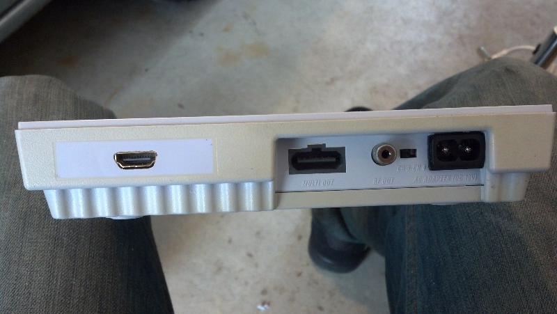
Dremmel, the tool of choice with a sanding and router bit. What you see is the rear power/av pannel of the SNES. With a steady hand, I shaped out the hole to fit my IEC-C7 socket. (The same one the PS3 uses.)

Just needed to clean the plastic slag off it and she is ready to go
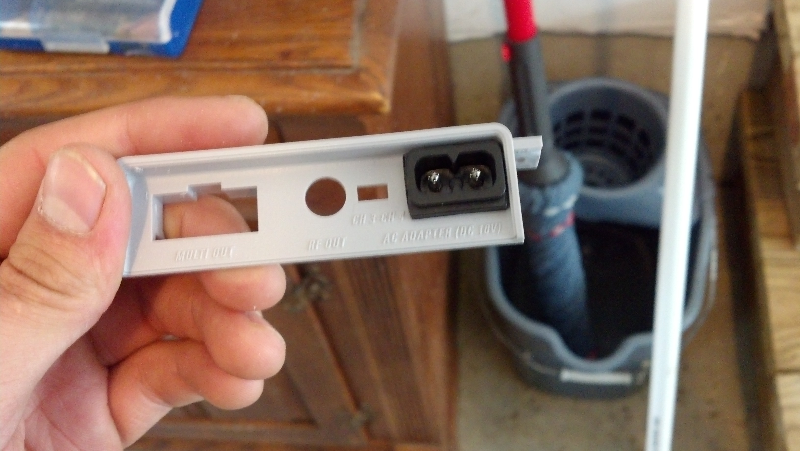
Boom! Legit! I could have shaped the Socket a bit better by putting some sandpaper on a flat surface and sliding the socket along it, but I was on a roll and was onto the next step. It was good enough for me!

She fit quite nicely on the board. I did have to unsolder the original adapter off the board to remove the panel to begin with, the rest was just cosmetics.
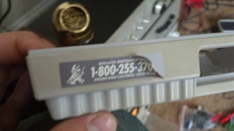
Time to peel of that 800 number sticker. Only to reveal the notable and eventual yellowing of the SNES case. This is where the HDMI port will go. There really was no choice either. The breadbox fit best there anyways.
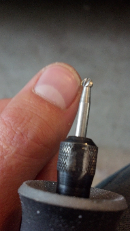
Now to use my favorite bit. Not sure what it's called but it makes nice for fine detailed shaping of plastics.
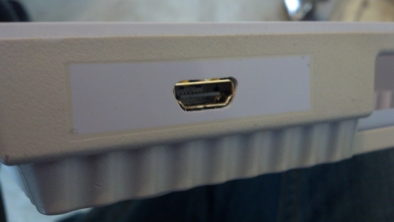
Not exactly the Mona Lisa, but hey, it was my first time making an HDMI-shaped hole.
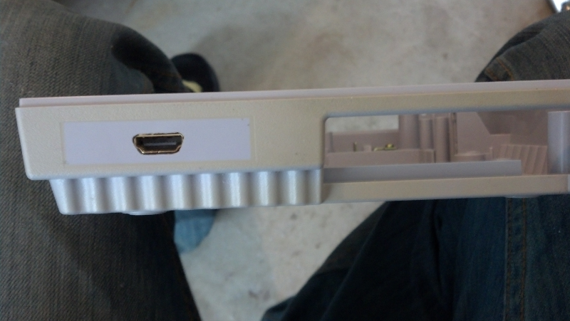
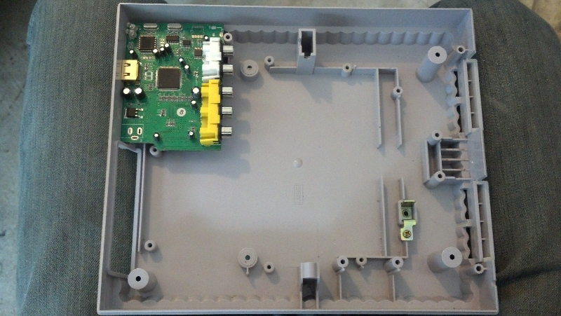
This is the component to HDMI board. Fits quite nicely. I did trim the fat off the sides of the board to help make it fit. I used my dremmel with a cutting wheel to do that.
Meh. I'm happy with it.

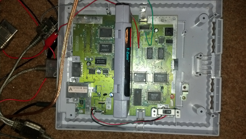
Next step! We go ahead and do the component mod off the S-ENC video chip and wire it to the component to HDMI breadbox. Be sure to tape those wires down, they will work themselves off! Also I used the wires from an ethernet cable. They were nice and small and suitable to work with. And make sure you tin the wires before hand!
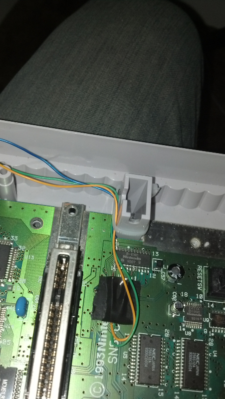
Zip tie that shiz! Serously though. Zip ties are your friend.

Next was to electrically insulate the bottom of the HDMI breadbox to prevent it from shorting out on the SNES board. Electrical tape did the trick nicely.
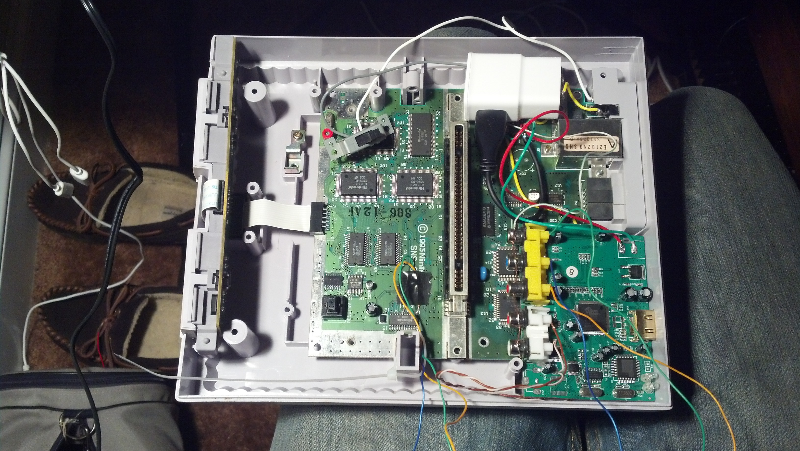
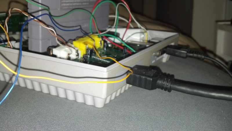
At this point I was on a super roll and forgot to pic it all. What happened here was I removed the 9v to 5v regulator (labled 7805) and replaced it with a Samsung tablet USB charger. Normally an iPod chrager would do, but they are only 5v 1A. I chose this because my component to HDMI board called for 5v 1A as well. How convienent! So the power supply I used puts out 5v 2A. Then I wired the SNES on/off switch to the 120AC off the IEC-C7 socket. Now the USB power supply shuts off, turning everything off.
I also wired the component output from the SNES to the converter. This was key, as most flat screens can see the component signal this outputs. But after being converted to a digital signal, it can!
Also wired here is the power and signal ground for the converter, as well as the stereo sound. I just tapped off the AV out for the sound. PINs 11 & 12 if I remember. I just metered it out to find em.
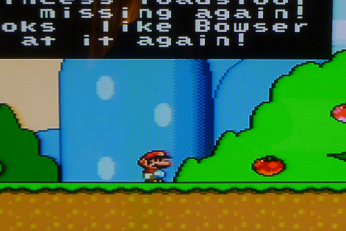
NOW TO TEST IT!!!
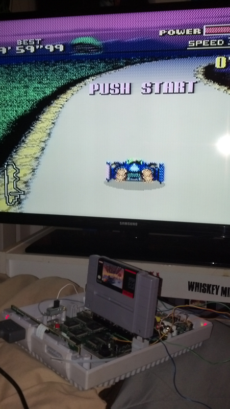
Legit. So, as predicted, the picture was a bit off colour.
So, what I've done since that picture was put a 100ohm resistor on the lumina (green), and put a 1uf capacitor on the red and blue signals. The picture now looks fantastic. Or well as fantastic as you can get with SNES. It's nice and sharp. Also It will be so much easier to bring a SNES around now. If someone has a PS3 then you can just swap the power chord and HDMI and you're ready to roll!
I plan to put a 3 pole, single throw switch in line with the component signals going to the converter that is accesable from the back side, so as to turn off the singals so the original multi AV can still be used and not have any signal loss. Then just button her up. And done!
Yeah!
**UPDATE 10/14/13**
Okay. So here's a comparison test of the same pause screen from composite, HDMI, and component, in that order. (mind that HDMI and component have 100ohm resistor on lumia and 1uf capacitor on red and blue to colour correct)
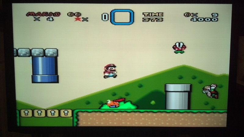
This is just plain old composite on a flatscreen.
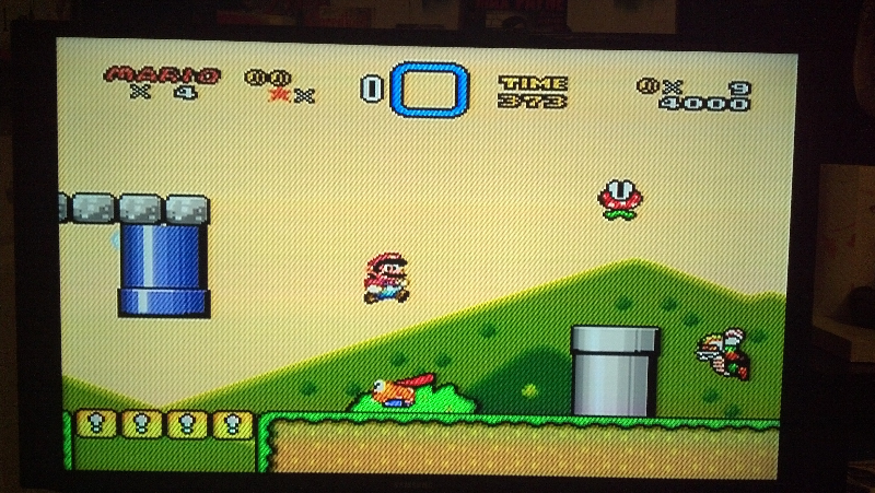
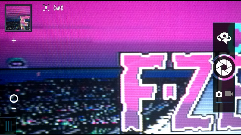
And now the HDMI (component to HDMI to be exact) The same TV and picture setting were used as was used on the composite signal. The reds are a bit more noticable, which can be altered. But the diagonal lines are heavily noticed. It's hard to tell from the pictures, but there is a noticable difference in the sharpness of the pixels. From here I knew now that these lines must be from the SNES component signal, or the converter.
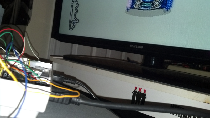
Then I pulled out the tube TV with component inputs...

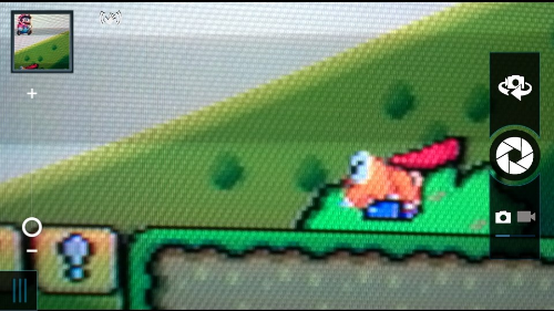
What you see here is a screenshot of my camera looking at the tube screen with component input. (the only way I could take it without a terrible flicker) The diagonal lines are seen in these pictures, though not as sharp (the TV's fault, not the signal). But they are there, and there's no doubt about it.
So these lines originate from the component signal and, somehow, are lost or filtered out along the way the composite signal. The only reason they are so noticable on the flat screen is the sharpness of the image. I'd really like to find a flatscreen that accepts 240p component to solidify this. I also still plan to try another converter just for the hell of it, but I truely believe that there is no way it's the converter.
The whole point of this project was to make the SNES easier to use in any situation. Not many people have tube TVs now, and HDMI is just more simple. But I really would like to be able to rid of those lines and not reduce image quality. I could go composite to HDMI, but that just seems like a fall back to me.
Let me know what you think, or any ideas I should try.
**UPDATE 10/17/13**
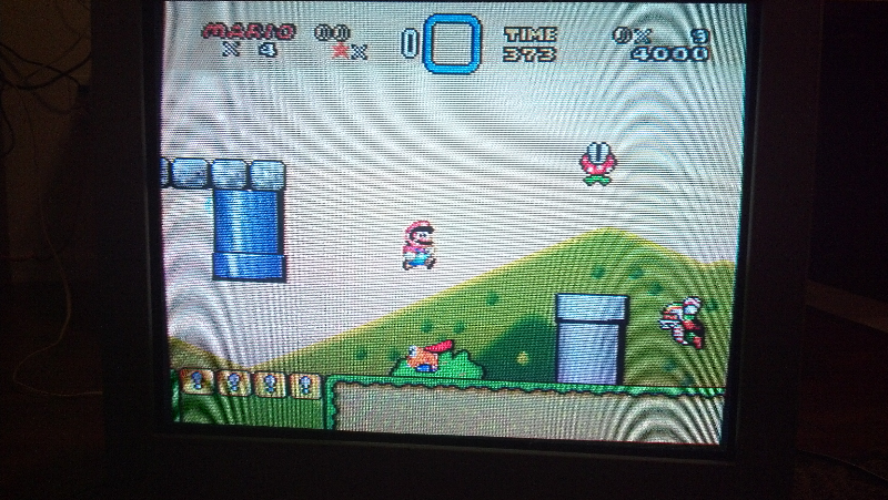
So I just tried my other SNES, with all orignal parts (i.e. power supply) to remove any factors. Mind that my other SNES is also a GPM-02 chipset. (which I now rue)
All I did here was the component mod tapping of the RGB chip, just like any other, and these are my results...

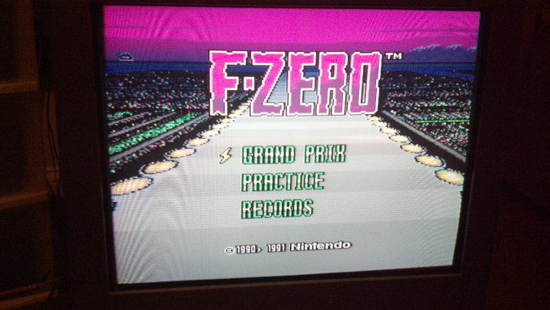
Note the diagonal lines are still present. That must be a signature of the GPM-02 chipset, at least that's how I feel. I can't widdle it down any further than this. I've removed all factors and isolated it to the chipset. I even tried tapping the Lumina off the composite/s-video AV out. It's always there, but strangly is not when using plain composite.
I would really like to get my hands on any other chipset type (besides the first one) and try all these tests again. I'd really like to have the best HDMI picture possible.
Any and all info and data on serial numbers or test results from other sources would be greatly appreciated.
I've reached a dead end for now, at least until I get my hands on another SNES or a different chipset. Time to hit up ebay and the local pawn shops!!
*note: Feel free to PM me anytime for any questions or whatever. I will gladly do my best to help! and if I can't then I will learn how to help you!